Reference
WFM 601A, WFM 601E & WFM 601M User Manual
3–37
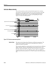
Jitter Measurement Display (WFM 601M Only)
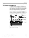
The Jitter display mode provides an automatic peak-to-peak measure of time
jitter on the active SER A or B input signal. Selectable high-pass filters allow
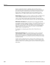
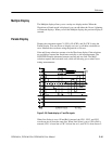
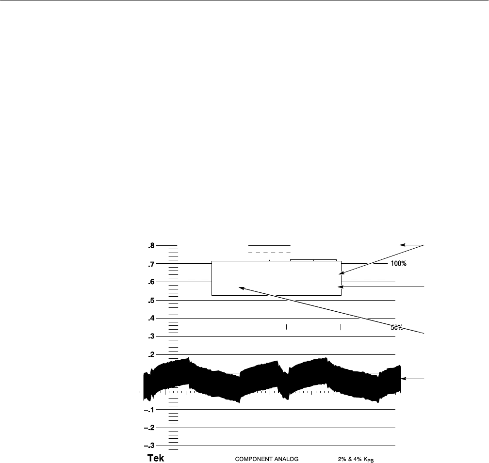
you to distinguish between high and low frequency jitter. Figure 3–27 shows an
example of the Jitter display including a sample jitter waveform. The jitter mode
converts any phase modulation to amplitude and plots it against time. An
unfiltered version of the jitter waveform appears on the JITTER OUT BNC
connector on the rear-panel.
Jitter measurements appear in the Jitter measurement box. The left measurement
is Timing or wideband peak-to-peak jitter from 10 Hz to 5 MHz. The right
measurement gives filtered peak-to-peak jitter measured after the high-pass filter.
The selected high-pass filter is indicated above the filtered jitter measurement.
0.1 UI/DIV 2 FIELD
10HZ
High-pass filter
Jitter p-p out of
high-pass filter
Jitter waveform
after the
high-pass filter
Wideband p-p
jitter
JITTER (P-P)
TIMING
0.16UI
10HZ HPF
0.17UI
Figure 3–27: Example of the Jitter display


