Reference
WFM 601A, WFM 601E & WFM 601M User Manual
3–53
Vector Display Modes
The waveform monitor provides two types of vector displays. One is a conven-
tional Vector display that plots the two color difference signals, Pb and Pr,
against each other. The Vector display is useful for checking the chrominance
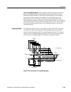
phase and amplitude. The second vector display is the Lightning display. The
Lightning display plots luminance (Y) versus Pb on the top and Y versus Pr on
the bottom. This display is useful for evaluating component signal amplitude and
timing.
Press the VECTOR/GAMUT button to select a Vector display. Press the lower
bezel button to select VECTOR or LIGHTNING modes.
Both vector modes can operate with 75% or 100% Color Bar signals. Press the
CONFIG MENU button and select the WFM/VEC menu to select the 75% or
100% graticule to match your test signal.
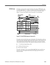
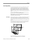
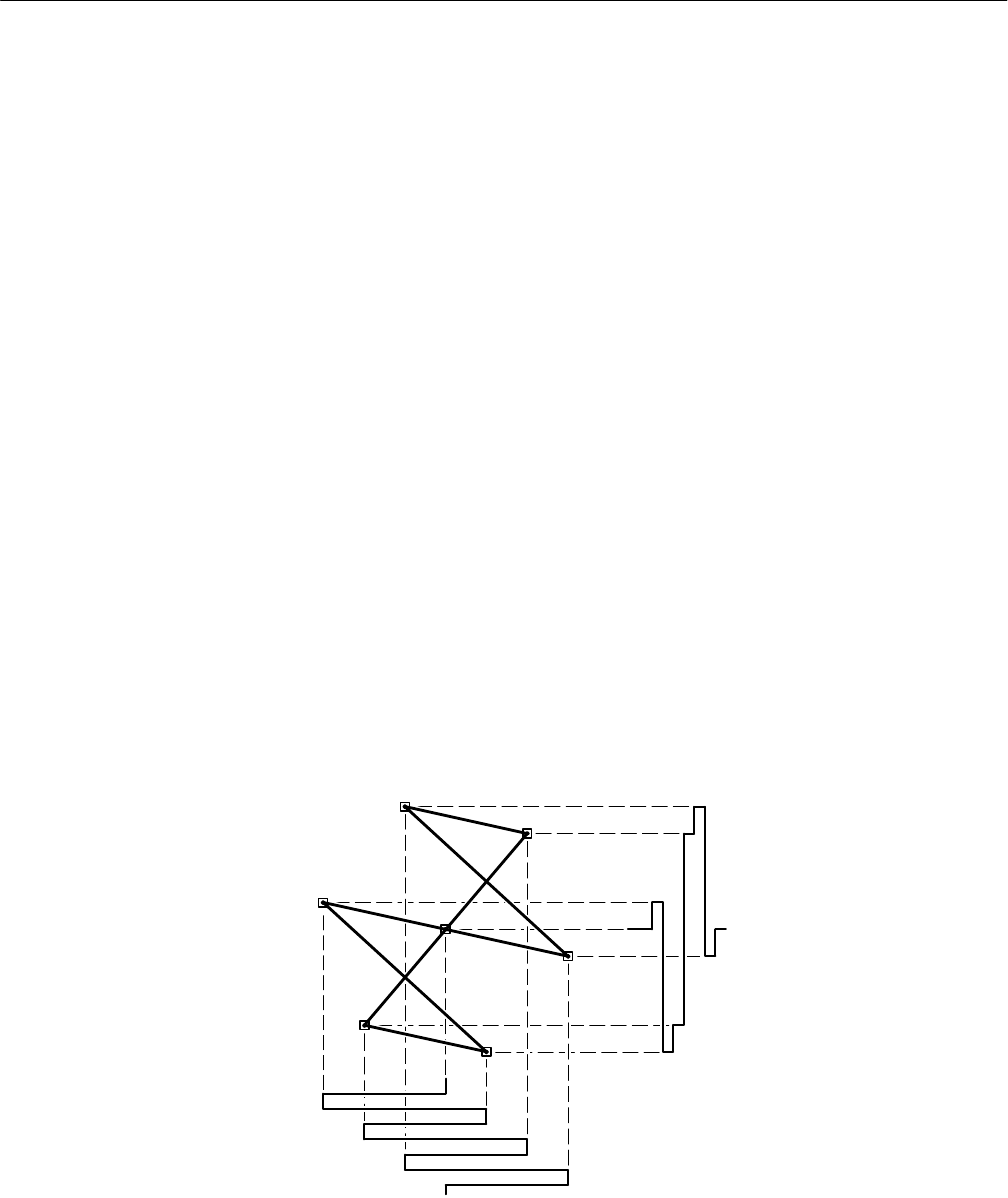
The Vector display plots the two color difference signals, Pb and Pr, against each
other, similar to a composite vectorscope. Figure 3–36 shows how the color
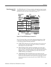
difference signals are plotted to create the Vector display. Figure 3–37 shows the
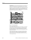
actual polar graticule with trace lines indicating how a trace would appear on the
graticule.
The polar display permits measurements of hue in terms of the relative phase of
the chrominance signal. Amplitude of chrominance is the displacement from
center (radial dimension of amplitude) towards the color point.
Pr signal
Pb signal
R
M
G
B
C
Y
G
Y
L
Figure 3–36: Vector display relationship of the Pr and Pb signals
Vector Display


