


Reference
WFM 601A, WFM 601E & WFM 601M User Manual
3–23
3. Use either the OVERLAY or 10-EYE display mode. Press the CONFIG
MENU button and select the EYE PATTERN menu to choose OVERLAY or
10-EYE.
4. Set CLOCK BW, in the Config EYE menu, to 1kHZ in order to reduce the
effects of time jitter, which can obscure the amplitude measurement.
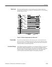
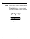
5. For graticule measurement, select X1 vertical gain and make sure that
variable gain is off. At X1 gain, the scale is 100 mV/div.
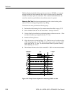
6. Use the VERT POS knob to position the waveform bottom at the 0 V line. If
the waveform exceeds 800 mV, position its bottom at the –.1, –.2, or –.3 V
line. Measure the amplitude at a horizontal part of the waveform top line.
7. Enable the Voltage Cursors.
8. Position one cursor at the top horizontal part of the waveform; ignore any
overshoot on the rising edge.
9. Position the second cursor at the bottom of the waveform; ignore any
undershoot. The Voltage Cursor readout gives the signal amplitude.
10. For Cursor measurements, you can use any gain setting, including variable
gain, since the waveform and the cursors are equally affected by the gain
setting. Use higher gain settings, such as X5, to help match the cursor to the
waveform.
Signal sources should measure 800 mV
p-p
"10%. Signal amplitudes outside this
range can degrade receiver performance.
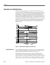
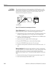
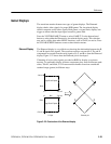
Measuring Aberrations. Serial sources should produce good signal transitions with
a minimum of overshoot and ringing. Automatic equalizer circuits in receivers
may be sensitive to aberrations greater than 10%.
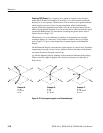
To measure aberrations, perform the following steps:
1. Perform the initial settings for Eye measurements described on page 3–22.
2. Enable the Voltage Cursors.
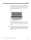
3. Place one cursor at the peak of the overshoot and the other at the bottom of
the topline of the waveform. Include any ringing (the oscillation following
overshoot) in the measurement. Essentially, you are measuring the thickness
of the top line of the waveform.
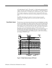
4. Perform the same cursor measurement on the bottom line thickness,
including any undershoot and ringing.
5. Aberrations at the top or bottom line should not exceed 10% of the signal
amplitude.