


Functional Overview
WFM 601A, WFM 601E & WFM 601M User Manual
2–7
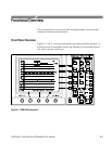
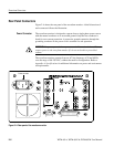
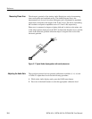
There are three passive loop-through inputs located on the rear panel. All are
compensated for 75 W impedance and require proper termination at one end of
the loop-through connector or at the receiver in a monitored system.
SER A and SER B. Provides for connection of two 270 Mb serial component data
signals. These inputs have minimal impact on the monitored serial data path.
EXT REF. Provides for connection of an external synchronization signal such as
black burst or composite video.
Five rear panel connections drive signals into a 75 W environment.
MON OUT (Y/G, P
B
/B, P
R
/R). Provides three 75 W component signal outputs to
drive a component picture monitor. You can set the output format to YP
B
P
R
or
GBR. Invalid input signals cause a blinking highlight of the monitor display at
the line where the error occurs. This gamut error highlight or “bright-up” signal
is present on the Y (or G) output and is controlled in the CONFIG menu.
SERIAL OUT. Provides a reclocked version of the selected signal input (SER A or
SER B).
JITTER OUT. (WFM 601M only) Provides a 75 W output signal from the jitter
demodulator. The Jitter high-pass filter (JITTER HPF) selection does not affect
this signal. You can view the jitter waveform on the waveform monitor using the
JITTER display mode.
Two multi-pin connectors provide control using a PC or other controller. Refer to
Appendix B for pin assignment information for these connectors.
RS-232. This 9-pin subminiature D-type connector provides a serial interface for
remote control and calibration.
REMOTE. This 25-pin subminiature D-type connector provides limited remote
control functions.
Loop-Through Inputs
Coaxial Outputs
Multi-Pin Connectors