


99
Kirby Morgan 37 & 57
© Copyright 1970-2008 Kirby Morgan Dive Systems, Inc. All rights reserved. Document # 080508001
The exhaust valves must be correctly
installed in the exhaust valve inserts or
they will not seal correctly. This could
lead to a backflow of water into the hel-
met, which could expose the diver to any
contaminants that are in the surrounding
water. Depending on the contaminants,
this could lead to serious personal injury
or death.
WARNING
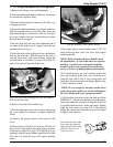
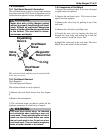
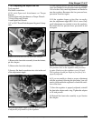
6) Slide the starboard whisker onto the starboard side
of the main body, making sure that you do not dis-
lodge the exhaust valve/whisker exhaust valve insert
assembly from its seating area. The parting line on
the bottom of the exhaust whiskers should be 5/16”
behind the parting line on the main body.
7) Repeat this procedure for the port side.
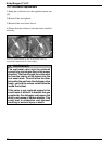
8) Place whisker clamps around the grooves on each
of the two whiskers. Before doing the final tightening
of the clamps, make sure that parting line on bot-
tom of wings is 5/16” behind the parting line on the
main body, and the clamps are positioned properly
on the body.
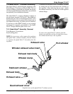
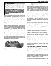
The correct orientation of the whiskers relative to
the exhaust main body are as shown in the photo
here. Tighten the screws that hold the clamps until
the screws are snug. The threaded ends of the screws
should be at least flush with the outer edge of the nut
that holds them. Do not overtighten.
The whiskers must be aligned properly on the exhaust
main body.
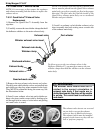
7.9.2.2 SuperFlow 350
Regulator Exhaust Valve
Replacement
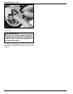
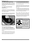
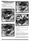
Before removing the regulator exhaust valve, care-
fully inspect the area around the edges to assure the
rubber exhaust valve is in contact with the regulator
body. The metal cross area of the body under the
valve could be slightly bent out resulting in the valve
not sealing.
If the exhaust valve is high and not sealing, lightly
press in on the metal cross, bending the metal in
slightly until the rubber valve seats. Remove the
existing regulator exhaust valve by pulling it out of
its mount hole. If the valve tears, make sure that it
is removed without any valve material left inside the
regulator.
NOTE: Before installing the new Valve, ensure that
the spokes that hold the exhaust Valve are smooth,
even and not bent. The Exhaust Valve seating area
should be free of dirt and corrosion to insure the
valve can lay flat and seal properly. NEVER lubricate
the valve.
1. Remove the regulator clamp screw and clamp.
3. Remove the regulator cover and the diaphragm.
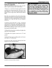
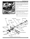
4. Install the new regulator exhaust valve by plac-
ing the stem of the valve in through the hole in the
hub of the spokes from the outside of the regulator.
Gently, (using needle nose pliers) from the inside of
the regulator, pull the stem of the valve through the
hole in the hub of the spokes until it pops into its
seating area.
5. Reinstall the diaphragm, regulator cover, clamp
and clamp screw.
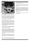
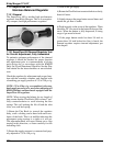
7.9.3 Quad-Valve™ Assembly Installation
1. The Quad-Valve™ Main Body opening mates to
the regulator exhaust flange. This opening needs to
be worked onto the flange. Make sure that the Quad-
Valve exhaust system is facing the correct direction
and is not upside down.
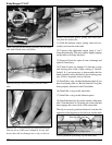
2. Place the tie wrap around the tie wrap groove and
tighten, making sure that the tie wrap end is positioned
properly. Cut off the excess tie wrap tail.
3) Reinstall the regulator/exhaust assembly on the
helmet.