


94
© Copyright 1970-2008 Kirby Morgan Dive Systems, Inc. All rights reserved. Document # 080508001
Kirby Morgan 37 & 57
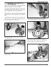
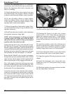
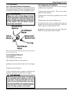
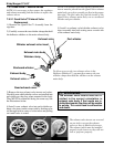
Alternate method: If a KMDSI tool kit is not avail-
able, a small jeweler’s screwdriver or metal scribe
can be inserted in the slot on the end of the inlet
valve to keep it from rotating, and needle nose pliers
may be used to rotate the lever nut. Holding the slot
of the inlet valve from rotating, carefully rotate the
nut “In” (clockwise to remove lever play and “Out”
(counterclockwise) to increase lever play.
Only turn the adjustment nut 1/8 turn at a time. De-
press the lever momentarily after each adjustment
and observe the lever play. It may be necessary to
complete this procedure several times, as the proce-
dure requires estimating the proper position of the
nut. If the regulator free flow did not stop after this
procedure, refer to regulator disassembly and cleaning
sections of this manual.
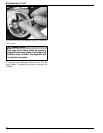
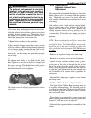
8) When adjustment is complete, place the diaphragm
and cover in place, and press tightly down on the cover
to simulate the action of the clamp.
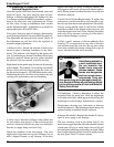
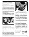
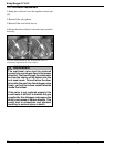
9) With the cover pressed tight against the diaphragm,
if the regulator starts to free flow, the lever may need
to be bent down slightly. If the regulator does not free
flow, slowly depress the purge button until a slight free
flow develops. The purge button should depress no
further than 1/8 inch (3.0 mm) before the regulator
develops a flow.
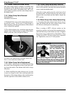
If the regulator does not develop a slight free flow
when the purge button is depressed in 1/8 inch (3.0
mm), then the lever will require slight upward bend-
ing.
Before bending the lever, double check the adjust-
ments. It is rare that the lever requires bending in
Press the cover over the diaphragm.
a regulator that has been in service. Usually levers
only require bending in new installations or because
of damage during disassembly.
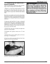
10) Install the clamp and clamp screw. Tighten the
screw to the correct torque (see appendix for torque
specifications).
11) Again, press on the purge button in the cover. It
must have 1/16 inch (1.5 mm) minimum and 1/8 inch
(3.0 mm) maximum free travel before it contacts the
diaphragm. If there is more than 1/8 inch (3.0 mm)
travel, the lever must be bent upward, per this chapter.
If the button has only slight or no free travel, the lever
must be bent down.
12) If the purge button travel is correct, the adjust-
ment is complete.