


82
© Copyright 1970-2008 Kirby Morgan Dive Systems, Inc. All rights reserved. Document # 080508001
Kirby Morgan 37 & 57
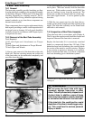
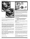
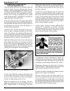
is over the hole. The adjustment knob can be held
against the wood block allowing the roll pin to be
driven into the 1/4” hole.
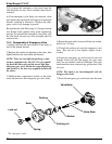
5) Remove the adjustment knob, the washer and O-
ring.
NOTE: If the spacer and the spring set are stuck,
this could indicate corrosion or possible saltwater
intrusion into the adjustment tube and assembly,
or that the adjustment tube is bent. The demand
regulator should be removed from the helmet and
cleaned and inspected, per this Chapter..
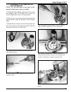
6) Carefully inspect all parts for corrosion, paying
particular attention to threaded surfaces and the
spring set. Clean and lightly lubricate parts per the
instructions in this chapter.
NOTE: Carefully inspect the adjustment shaft to
ensure it is straight, Check for damaged threads.
Replace the adjustment shaft if any damage is
found. Replace the O-ring.
7) Replace washer.
8) Replace the O-ring.
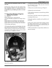
Shake out the spacer, spring set, and piston.
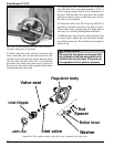
9) Inspect the inside of the adjustment tube on the
regulator body to be sure there is no corrosion and
the adjustment assembly can travel freely. Ensure the
alignment tube is not bent or misaligned from impact,
and that the threads are clean.
NOTE: If the inside of the adjustment tube is cor-
roded, this indicates saltwater intrusion into the
adjustment tube and assembly. The demand regula-
tor requires removal from the helmet and cleaning
per this Chapter.
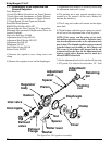
7.7.5 Reassembly of the SuperFlow 350
Regulator Adjustment System
Tools Required:
3/4 inch Open-end Wrench Attachment on Torque
Wrench
Silicone grease, or oxygen compatible grease if used
for oxygen service.
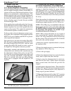
1) Lightly lubricate the piston and spacer and place
the piston back in the regulator adjustment tube, fol-
lowed by the spring set, and spacer.
2) Lightly lubricate the adjustment shaft end and
threads, install the washer and the lightly lubricated
O-ring on the adjustment shaft.
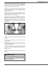
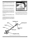
3) Slip the packing nut over the adjustment shaft fol-
lowed by the adjustment knob.
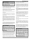
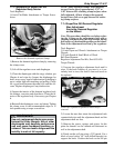
4) Hold the shaft and rotate the knob until the pin
holes line up. Use the inlet valve holder from the
regulator tool kit to accurately align these holes. Us-
ing a small hammer drive the retaining pin back into
place, until it is flush with the surface of the adjust-
ment knob.
5) Screw the adjustment knob assembly clockwise
back into the regulator body leaving enough packing
nut exposed to get the wrench on it.
Inspect the washer and o-ring.