


77
Kirby Morgan 37 & 57
© Copyright 1970-2008 Kirby Morgan Dive Systems, Inc. All rights reserved. Document # 080508001
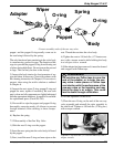
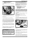
and rotate the stem all the way out, then back again.
The rotation must be smooth. If “hard spots” or un-
evenness are felt during the rotation, the stem may
be bent and could need replacement.
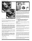
8) Tighten the packing nut with a torque wrench until
moderate resistance is felt when turning the knob.
Torque to 50 inch pounds after seating.
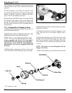
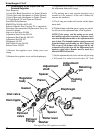
9) Place the spring, and locknut onto the stem secur-
ing the knob.
10) Tighten the locknut until its top is flush with the
top of the knob. The assembly is now complete and
ready for testing.
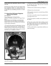
NOTE: If the valve was removed from the side block
testing of the emergency gas valve is easily accom-
plished by attaching the valve, by itself in the shut
position, on to the bail-out whip from the first stage.
Pressurized to a minimum 135 p.s.i.g. (9.3 bar) us-
ing the EGS Cylinder and dropping it into a bucket
of clean water a minimum 30 seconds to check for
leaks.
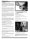
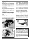
11) Before wrapping the threads with pipe tape, check
the fit of the valve assembly pipe threads to the mating
threads of the side block. There should be 2 turns of
hand make up before needing to use a wrench.
A leaking Emergency Gas Valve assembly
can cause the diver to exhaust his entire
EGS (bailout) without his knowledge. This
may lead the diver to mistakenly assume
his EGS supply is available when it is
not. This could lead to panic or drowning
in an emergency. Any worn or damaged
components must be replaced.
A submersible pressure gauge
should always be used with the EGS sys-
tem to help minimize this risk.
WARNING
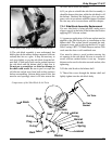
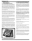
the first thread. Apply the tape with slight tension to
allow the tape to fill into the threads.
Hand tighten the valve, then continue an additional 1-1/2
to 2 turns with a wrench keeping in mind the proper
alignment of the control knob to the side block. Also,
there should be at least one male thread visible. Check
to be certain the valve is tight by trying to loosen the
fit by hand.
DO NOT TIGHTEN
THE VALVE BODY TIGHTER
TH
AN NECESSARY!
OVER TIGHTENING MAY
OVERSTRESS THE PART AND CAUSE THE PART
TO FAIL.
It is NOT necessary to have the control knob for the
emergency gas supply valve perfectly “square,” i.e., at
a 90 degree angle to the side block. Any angle is ac-
ceptable provided that 1) the valve handle can be turned
easily and 2) the diver can locate the handle easily.
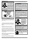
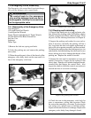
7.5.4 Leak Testing the EGS Valve
a) Attach supply whip from the EGS first stage to EGS
helmet valve.
b) Ensure the defogger valve knob is open and the EGS
Valve is shut.
c) Pressurize EGS Valve to a minimum of 135 p.s.i.g.
(9.3 bar) using the EGS cylinder as supply. Allow sys-
tem pressure to stabilize, and then shut the EGS supply
cylinder valve. Note time and final stabilized system
pressure.
d) Perform the leak check for minimum of five min-
utes, using the mild soapy solution, per Chapter 6.
Ensure there is no gas flowing or pressure drop in the
system. There should be no visible signs of external
leakage if the valve is operating properly.
The control knob for the emergency
valve and the defogger knob are not in-
terchangeable. Use only the correct knob
for the appropriate valve.
WARNING
Use only thin Teflon tape when installing
the Emergency Gas Supply valve in the
side block. Thick tape can lead to thread
damage, which may make it impossible
to install the EGS valve in the side block
properly. This could lead to a loss of
breathing gas.
WARNING
If there is less make up, then the threads will need to be
chased with a 1/4” NPT tap to obtain the proper make
up. If thread chasing is required, the bent tube assembly,
the one way valve assembly and steady flow components
must all be removed and the side block body must be
thoroughly cleaned to remove any loose particles.
12) Before installing the valve assembly, wrap the pipe
threads with 1-1/2 turns of Teflon tape starting after