


70
© Copyright 1970-2008 Kirby Morgan Dive Systems, Inc. All rights reserved. Document # 080508001
Kirby Morgan 37 & 57
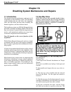
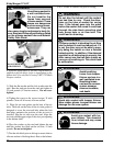
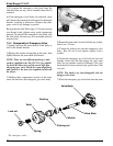
7.3 Side Block Assembly
7.3.1 General
The side block should be overhauled at least annually,
or whenever components show signs of wear, damage
or do not function smoothly or properly. Minimum
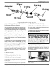
replacement components during overhaul includes
all O-rings. A repair kit is available for replacement
parts (Part #525-311).
The side block does not require removal from the
helmet each time an overhaul is being conducted
providing inspection of the internal passages does not
reveal contamination or excessive corrosion. How-
ever, the side block should be completely removed at
least every three years of active use to ensure fasteners
are not corroded or frozen.
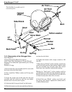
The side block assembly is held in place on the helmet
shell by a stud, flat washer, lock washer, nut, and a
machine screw. The screw does some securing but its
main function is to prevent rotation of the side block.
The stud also extends into the interior of the helmet
shell far enough to secure the air train by means of
the washer and nut.
The air train cup that fits over the stud is made of
soft brass and cannot be used for a bearing surface to
mount the side block. RTV silicone rubber compound
is used to form a gas tight seal between the side block
and the exterior of the helmet shell.
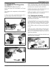
7.3.2 Side Block Assembly Removal
Tools Required:
7/16,11/16, and 7/8 inch Open End Wrenches
11/16 and 7/8 inch Open End Wrench Attachment on
Torque Wrench
1/4 inch Flat Blade Stubby Screwdriver
The bent tube assembly must be entirely removed be-
fore removal of the side block assembly is started.
1) Completely unscrew the bent tube assembly nut
(14) from the side block.
2) Using two wrenches, hold the nut at the regulator
end of the bent tube assembly with the first wrench.
With the other wrench, loosen the jam nut (100) by
turning the wrench DOWN.
3) Unscrew the bent tube nut until it comes free, then
pull the bent tube assembly straight out of the regula-
tor inlet nipple.
4) The side block assembly is ready to be separated
from the helmet shell at this time.
7.3.3 Separating the Side Block Assembly
from the Helmet Shell
Tools Required:
Putty Knife
7/16 inch Open End Wrench
1/4 inch Flat Blade Stubby Screwdriver
1) Removal of the side block assembly requires re-
moving the air train.
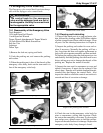
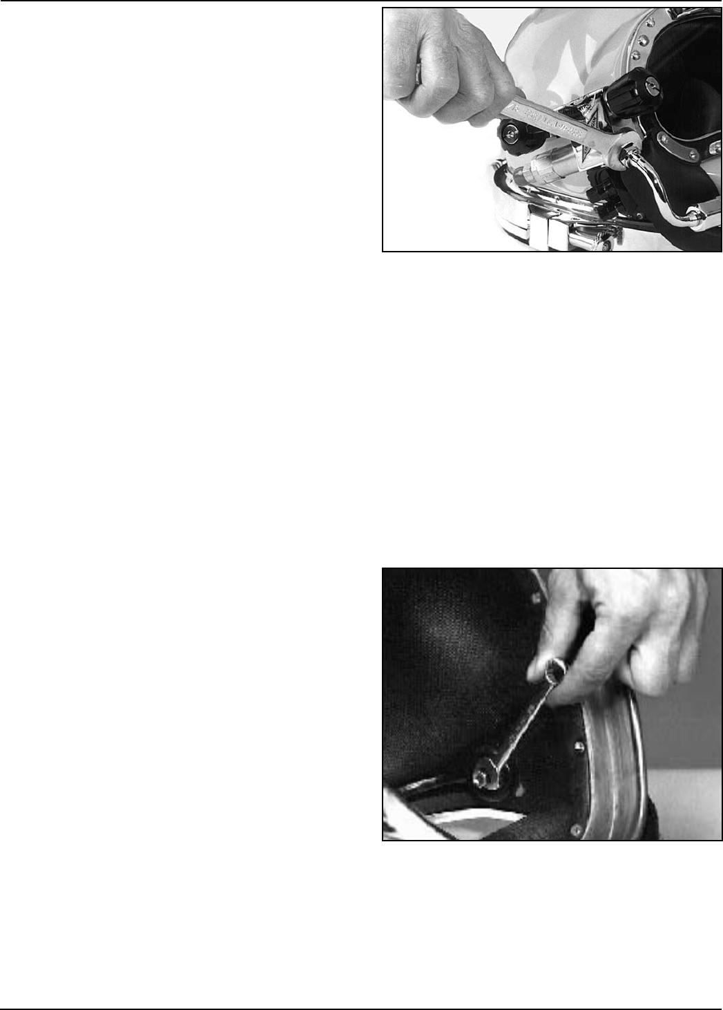
2) Remove the nut and washer that secure the air train,
then the air train itself.
3) The stud nut is removed next, with the lock washer
and flat washer.
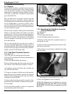
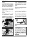
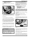
Loosening the nut that holds the air train.
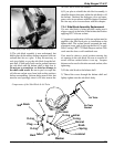
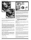
Loosening the bent tube from the side block.
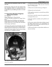
4) Next, the alignment screw is removed.
NOTE: The alignment screw is located in a recess in
the fiberglass next to the stud. This recess is normally
filled with RTV. The RTV must be scraped free to reveal
the screw.