


43
T
R
A
N
S
P
O
R
T
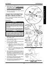
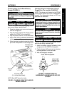
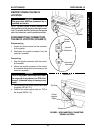
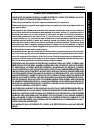
TRANSPORT PROCEDURE 11
Rear Frame
Assembly
Front Frame
Assembly
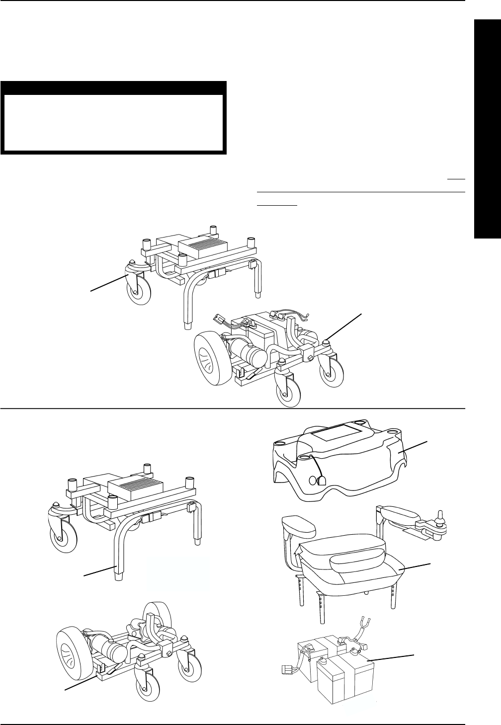
STEP 11
DISASSEMBLED VIEW
Shroud
Seat
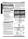
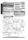
7. Disconnect the battery connector from the
controller connector.
8. Disconnect the RED and BLACK circuit
breaker cables from the circuit breaker.
WARNING
When reassembling the wheelchair, ensure the
retaining pins securing the frame assemblies
together are properly engaged and locked.
Otherwise, injury and/or damage may result.
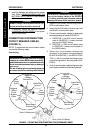
9. Release the two (2) retaining pins locks by
performing the following steps:
A. Bend the END of the retaining pin lock
AWAY from the retaining pin until it is clear
of the retaining pin (DETAIL "A").
B. While performing STEP A, swivel the re-
taining pin lock away from the retaining pin
(DETAIL "A").
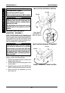
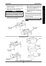
10. Remove the two (2) retaining pin that secures the
rear frame assembly to the front frame assembly.
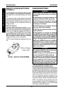
11. Separate the front frame assembly from the
rear frame assembly.
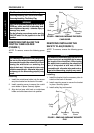
12. Remove the batteries with cables. Refer to
RE-
MOVING/INSTALLING THE BATTERIES WITH
CABLES in PROCEDURE 8 of the manual.
Front Frame
Assembly
Batteries
With
Cables
Rear Frame
Assembly
FIGURE 2 - TRANSPORTING THE WHEELCHAIR