


27
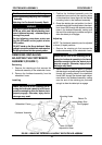
This Procedure Includes the Following:
Removing/Installing/Adjusting the Footboard
Assembly
Adjusting the Footboard Assembly Depth
F
O
O
T
B
O
A
R
D
A
S
S
E
M
B
L
Y
FOOTBOARD ASSEMBLY PROCEDURE 7
WARNING
After ANY adjustments, repair or service and BE-
FORE use, make sure that all attaching hard-
ware is tightened securely - otherwise injury or
damage may result.
For the following procedures, make sure
the ON/OFF switch on the joystick is in the
OFF position.
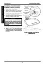
DO NOT stand on the flip-up footboard. When
getting in or out of the wheelchair, make sure that
the flip-up footboard is in the upward position .
REMOVING/INSTALLING/
ADJUSTING THE FOOTBOARD
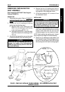
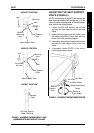
ASSEMBLY (FIGURE 1)
Removing
1. Remove the retaining pin that secures the
footboard assembly to the wheelchair frame.
2. Remove the footboard assembly from the
wheelchair frame.
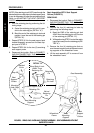
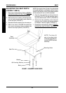
Installing
WARNING
Ensure that the end of the retaining pin se-
curing the footboard assembly to the frame
protrudes enough to allow the detent pin to
properly engage. Otherwise, injury and/or
damage may result.
1. Position the footboard assembly onto the
wheelchair frame so that the mounting holes
in the wheelchair frame align with the desired
mounting holes in the footboard assembly.
2. Grasp the retaining pin and position it so that it
passes through the mounting holes in the wheel-
chair frame AND through the desired mounting
holes in the footboard assembly, making sure
the end of the retaining pin protrudes enough to
allow the detent pin to engage.
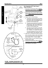
Adjusting
NOTE: The footboard assembly can be adjusted
to three (3) depth positions.
1. Remove the retaining pin that secures the
footboard assembly to the wheelchair frame.
WARNING
Ensure that the end of the retaining pin se-
curing the footboard assembly to the frame
protrudes enough to allow the detent pin to
properly engage. Otherwise, injury and/or
damage may result.
2. Adjust footboard to desired depth by grasping
the retaining pin and positioning it so that it passes
through the mounting holes in the wheelchair
frame AND through the desired depth adjust-
ment holes in the footboard assembly, making
sure the end of the retaining pin protrudes
enough to allow the detent pin to engage.
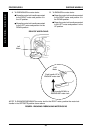
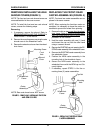
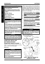
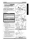
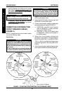
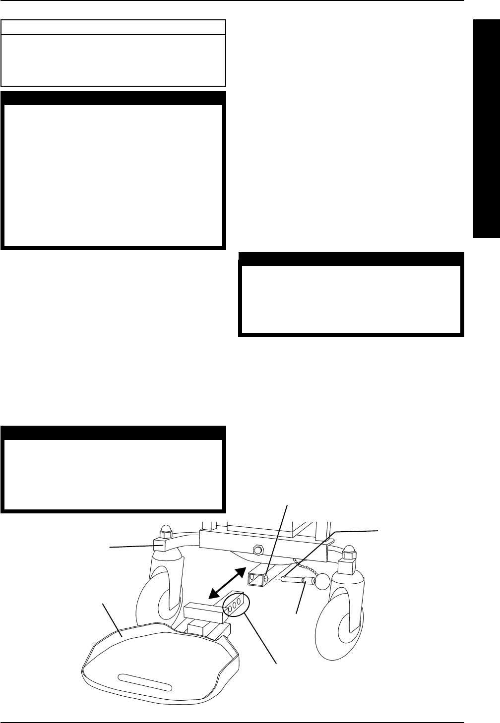
FIGURE 1 -REMOVING/INSTALLING/ADJUSTING THE FOOTBOARD ASSEMBLY
Wheelchair Frame
Retaining
Pin
Footboard Assembly
Three (3) Depth
Adjustment Holes
Mounting Holes
Detent Pin
(Make Sure
This Engages)