


20
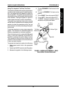
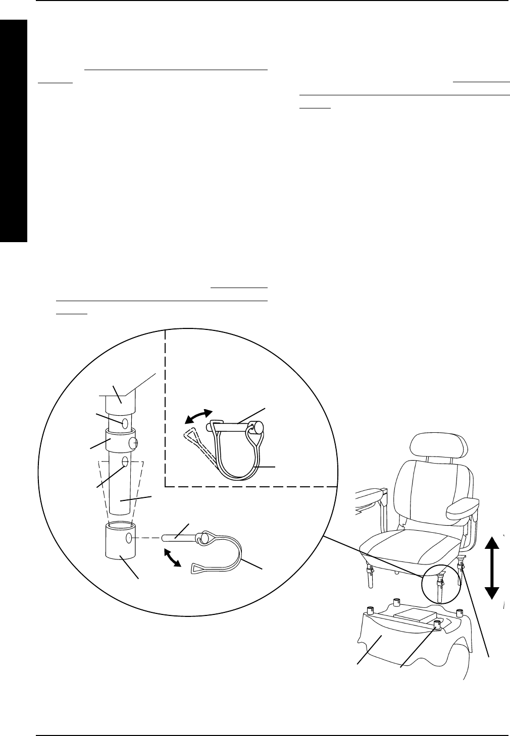
Seat Assemblies WITH Seat Support
Collars (FIGURE 3)
REMOVING.
1. Disconnect the joystick. Refer to
CONNECT-
ING/DISCONNECTING THE MKIV JOY-
STICK in PROCEDURE 9 of this manual.
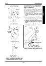
2. Release the four (4) retaining pin locks by
performing the following steps:
A. Bend the END of the retaining pin lock
AWAY from the retaining pin until it is clear
of the retaining pin (DETAIL "A").
B. While performing STEP A, swivel the retain-
ing pin lock away from the retaining pin (DE-
TAIL "A").
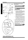
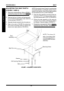
3. Remove the four (4) retaining pins that se-
cure the seat support posts to the seat mount-
ing supports on the wheelchair frame.
4. Lift the seat assembly UP to remove it from
the wheelchair frame.
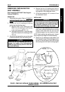
Seat
Mounting
Support
Seat Assembly
Wheelchair
Frame
Retaining
Pin Lock
Retaining Pin
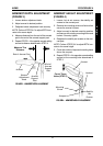
FIGURE 3 - REMOVING/INSTALLING THE SEAT ASSEMBLY - SEAT ASSEMBLIES WITH SEAT
SUPPORT COLLARS
Bend End of Lock
AWAY From
Retaining Pin
Seat
Support
Collars
Seat
Support
Collars
Welded
Collar
Retaining
Pin
Seat Mounting
Support
Mounting
Hole (Step
3A)
Seat Support Post
DETAIL "A"
Swivel
Retaining
Pin
Lock
S
E
A
T
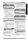
SEATPROCEDURE 5
NOTE: If the retaining pin will NOT pass through the
desired height mounting hole in the seat support post,
it may be necessary to adjust the seat support post.
Refer to ADJUSTING THE SEAT SUPPORT
POSTS in this procedure of the manual.
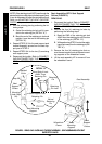
3. Lock the retaining pins by performing the fol-
lowing steps:
A. Swivel the retaining pin lock until it is par-
allel to the retaining pin (DETAIL "A").
B. Bend the end of the retaining pin lock and
position it over the end of the retaining pin
(DETAIL "A").
4. Repeat STEPS 2-3 for the seat support post
located diagonally across from the seat sup-
port post in STEP 2.
5. Repeat STEPS 2-4 for the two (2) remaining
seat support posts.
6. Reconnect the joystick. Refer to
CONNECT-
ING/DISCONNECTING THE MKIV JOY-
STICK in PROCEDURE 9 of this manual.
Step 3B