


14
W
H
E
E
L
C
H
A
I
R
WHEELCHAIR OPERATIONPROCEDURE 3
O
P
E
R
A
T
I
O
N
This Procedure Includes the Following:
Wheelchair Operation
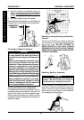
WHEELCHAIR OPERATION
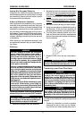
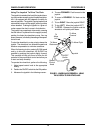
Switches/Indicators (Figure 1)
The following switches and indicators are located
on the joystick housing:
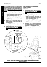
ON/OFF SWITCH - The on/off switch is located on
the BACK of the joystick housing. This two (2) posi-
tion toggle switch is used for turning the wheelchair
ON and OFF (DETAIL "B").
SPEED CONTROL KNOB - The speed control knob
is located on the BACK of the joystick housing. This
rotary knob is used for controlling the maximum
speed of the wheelchair. Turning the knob clock-
wise INCREASES the maximum speed of the wheel-
chair. Turning the knob counter-clockwise DE-
CREASES the maximum speed of the wheelchair
(DETAIL "B").
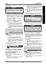
BATTERY DISCHARGE INDICATOR (BDI) - The
battery discharge indicator is located at the FRONT
of the joystick housing. It provides information on
the remaining charge in the batteries. At full charge
the BDI will be Green. As the battery becomes dis-
charged, the BDI will become Yellow (Amber), then
Red and finally the BDI will flash ON and OFF Red.
At this level, the user should charge the batteries as
soon as possible (DETAIL "C").
The BDI will flash ON and OFF Yellow to indicate a
reduced speed or power output.
The BDI also serves as a system diagnostic device
when a fault is detected by the control module. A
specific number of Green flashes will indicate the
type of fault detected. For more information on us-
ing the battery discharge indicator as a system diag-
nostic device, contact a qualified technician.
NOTE: When reading the Battery Discharge Indica-
tor (BDI), the joystick MUST be in the NEUTRAL
position for an accurate reading.
WARNING
After ANY adjustments, repair or service and
BEFORE use, make sure that all attaching
hardware is tightened securely - otherwise
injury or damage may result.
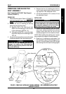
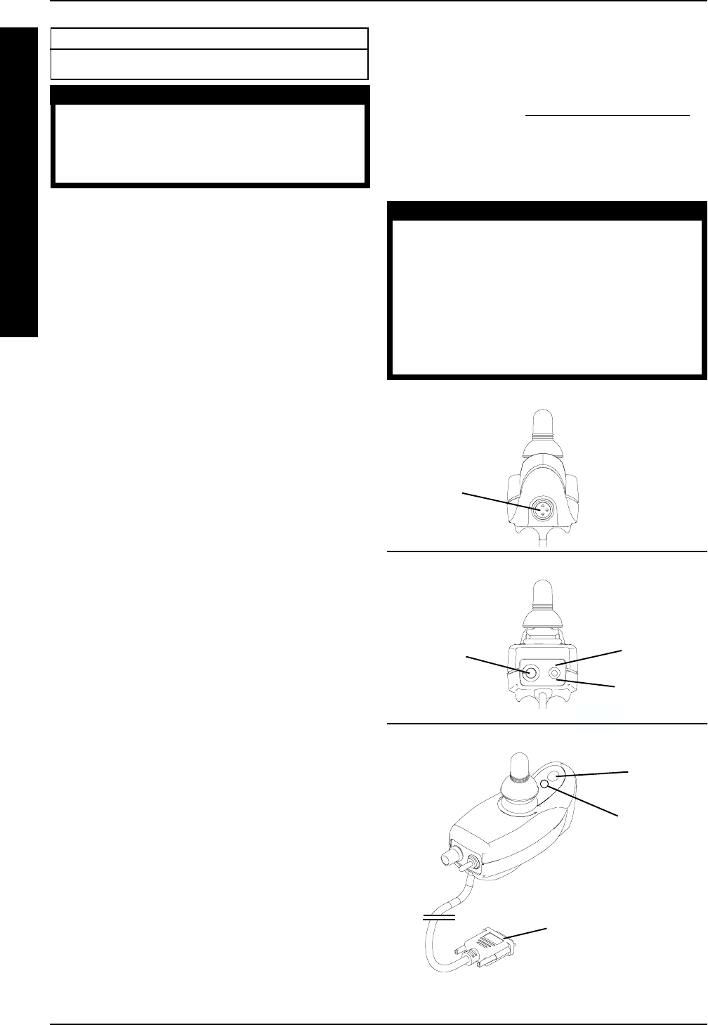
MULTI FUNCTION CHARGER PORT- The multi
function charger port is located at the front of the
joystick housing. It provides access for charging the
wheelchair batteries using an INDEPENDENT bat-
tery charger, refer to CHARGING BATTERIES in
PROCEDURE 8 of this manual. This port also serves
as the Remote Programmer/AVS communication
connection and is used for setting-up/programming
the electronic control unit (DETAIL "A").
WARNING
Set-up/programming of the Electronic Con-
trol Unit is to be performed ONLY by a quali-
fied technician. The fine tuning adjustments
of the controller may affect other activities of
the wheelchair. Damage to the equipment
could occur under these circumstances. If
unqulaified individuals perform any work on
these units, the warranty is voided.
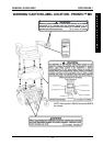
FIGURE 1 - WHEELCHAIR OPERATION -
SWITCHES/INDICATORS
On Switch
Position
Battery
Discharge
Indicator
Off Switch
Position
DETAIL "A" - FRONT VIEW
DETAIL "B" - REAR VIEW
Multi-
Function
Charger
Port
Speed
Control
Knob
Horn
DETAIL "C"
To Controller