


31
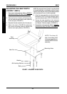
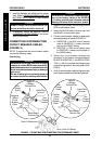
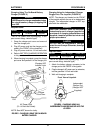
REPLACING THE FRONT/REAR
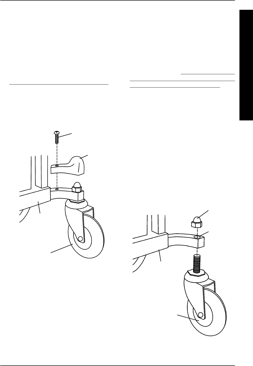
CASTER ASSEMBLIES (FIGURE 4)
NOTE: Front and rear caster assemblies are re-
placed in the same manner.
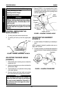
NOTE: When replacing the front/rear caster as-
semblies, it is necessary to brace the caster as-
semblies to prevent the wheel from spinning.
1. Remove the fork or stem cover from the wheel-
chair frame. Refer to REMOVING/INSTALL-
ING THE FORK AND STEM COVERS in this
procedure of the manual.
2. Hold the caster assembly with one (1) hand
and loosen the cap nut with the other hand
using a crescent wrench.
3. Remove the EXISTING cap nut securing the EX-
ISTING caster assembly to the wheelchair frame.
4. Remove the EXISTING caster assembly from
the wheelchair frame.
5. Position the NEW caster assembly in the
mounting hole in the wheelchair frame.
6. Secure the NEW caster assembly to the
wheelchair frame with the NEW cap nut. Se-
curely tighten.
7. If necessary, repeat STEPS 1-4 for the re-
maining three (3) caster assemblies.
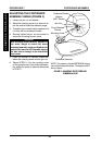
FIGURE 4 - REPLACING THE FRONT/REAR
CASTER ASSEMBLIES
Cap Nut
Caster
Assembly
Wheelchair
Frame
Mounting
Hole
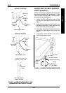
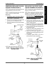
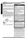
REMOVING/INSTALLING THE AXLE
SHROUD COVERS (FIGURE 3)
NOTE: The front and rear axle shroud covers are
removed/installed in the same manner.
NOTE: To install the front and rear axle shroud
covers, reverse the following steps.
Removing
1. If necessary, remove the shroud. Refer to
REMOVING/INSTALLING THE SHROUD in
PROCEDURE 7 of the manual.
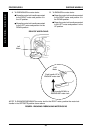
2. Remove the mounting screw securing the axle
shroud cover to the wheelchair frame.
3. Remove the axle shroud cover from the wheel-
chair frame.
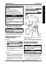
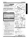
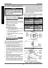
FIGURE 3 - REMOVING/INSTALLING THE FORK
AND STEM COVERS
Caster
Assembly
Wheelchair
Frame
Mounting Screw
Front
Axle
Shroud
Cover
SHROUD/WHEELS PROCEDURE 8
S
H
R
O
U
D
/
W
H
E
E
L
S
NOTE: Rear axle shroud cover NOT shown.