


29
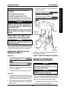
This Procedure Includes the Following:
Replacing the Foam Filled Tires onto the
Wheel Rim
Removing/Installing the Shroud
Engaging/Disengaging Motor Locks
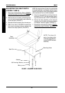
Removing/Installing the Axle Shroud Covers
Replacing the Front/Rear Caster Assemblies
SHROUD/WHEELS PROCEDURE 8
WARNING
After ANY adjustments, repair or service and BE-
FORE use, make sure that all attaching hard-
ware is tightened securely - otherwise injury or
damage may result.
For the following procedures, make sure the
ON/OFF switch on the joystick is in the OFF
position.
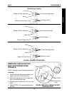
REPLACING THE FOAM FILLED
TIRES ONTO THE WHEEL RIM
WARNING
This procedure MUST be performed by a
qualified technician.
NOTE: During initial use of the wheelchair, the user
may experience flat spots on the wheels. Flat spots
will vanish with continued use of the wheelchair.
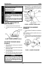
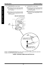
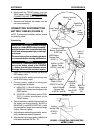
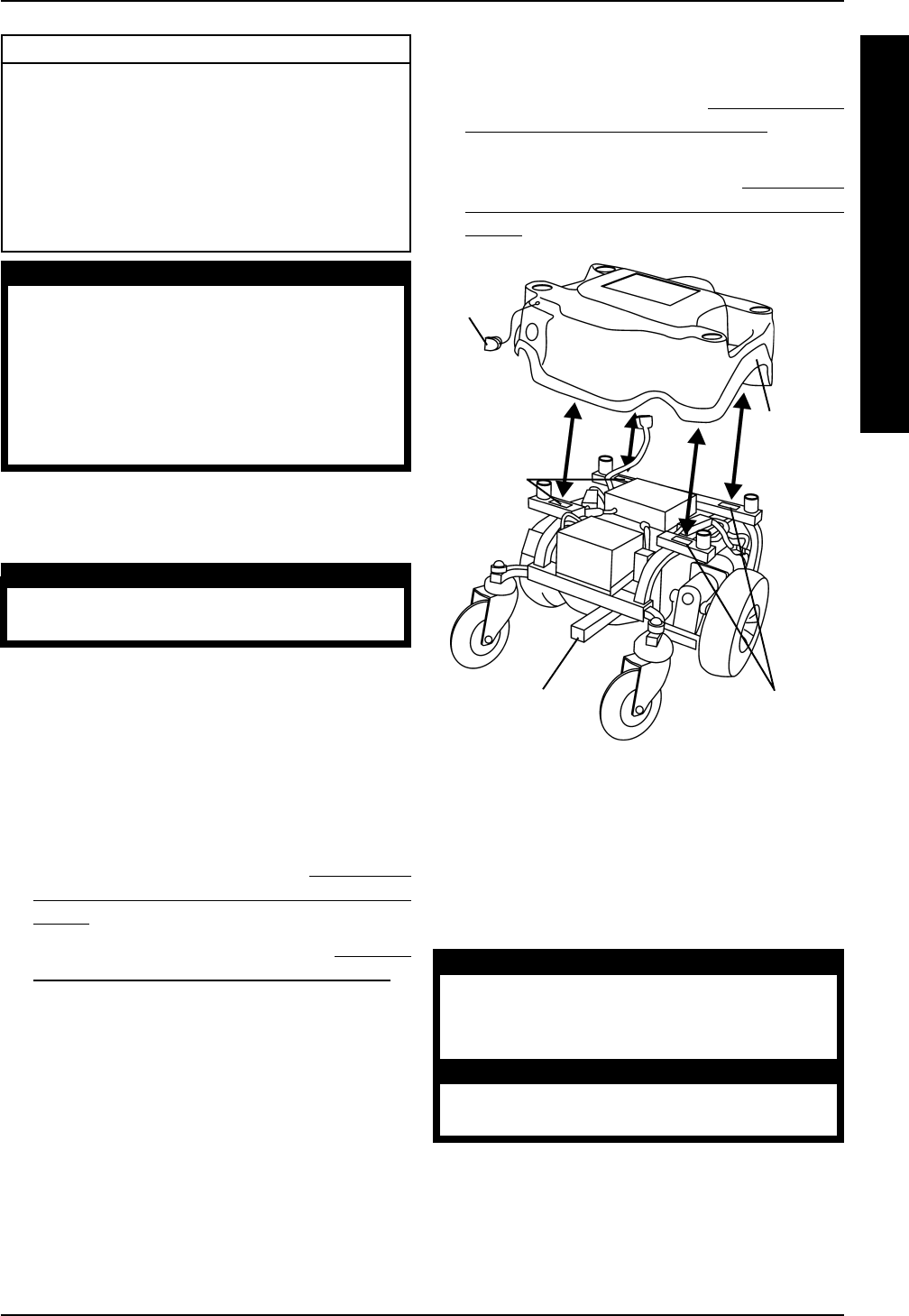
REMOVING/INSTALLING THE
SHROUD (FIGURE 1)
Removing
1. Disconnect the joystick. Refer to
CONNECT-
ING/DISCONNECTING THE MKIV JOY-
STICK in PROCEDURE 9 of the manual.
2. Remove the seat assembly. Refer to
REMOV-
ING/INSTALLING THE SEAT ASSEMBLY in
PROCEDURE 4 of the manual.
3. Grasp the charger port cover and remove it
from the charger port.
4. Lift the shroud off of the wheelchair frame.
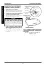
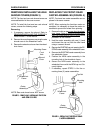
Installing
1. Align the four (4) hook and loop fasteners on the
underside of the shroud with the four (4) hook
and loop fasteners on the wheelchair frame.
2. Firmly push the shroud onto the wheelchair
frame, making sure the hook and loop fas-
teners meet.
S
H
R
O
U
D
/
W
H
E
E
L
S
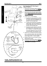
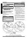
FIGURE 1 - REMOVING/INSTALLING THE SHROUD
Shroud
Wheelchair
Frame
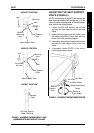
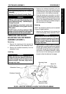
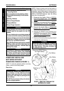
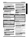
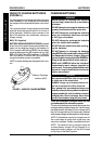
ENGAGING/DISENGAGING
MOTOR LOCKS (FIGURE 2)
WARNING
DO NOT engage or disengage the motor
locks until the ON/OFF switch on the joy-
stick is in the OFF position.
CAUTION
Ensure both motor locks are fully engaged
BEFORE driving the wheelchair
NOTE: The motor lock disengagement/engage-
ment allows freewheeling OR joystick controlled
operation. Freewheeling allows an attendant to
maneuver the wheelchair WITHOUT power.
1. Locate the motor lock handles on the motors.
2. Perform one (1) of the following:
NOTE: Hook and loop fasteners under shroud
NOT shown for clarity
Hook and
Loop
Fasteners
Hook and
Loop
Fasteners
3. Grasp the charger port cover and position it
in the charger port.
4. Reinstall the seat. Refer to
REMOVING/IN-
STALLING THE SEAT ASSEMBLY in PRO-
CEDURE 4 of the manual.
5. Reconnect the joystick. Refer to
CONNECT-
ING/DISCONNECTING THE MKIV JOY-
STICK in PROCEDURE 9 of the manual.
Charger
Port
Cover