


42
T
R
A
N
S
P
O
R
T
TRANSPORTPROCEDURE 11
This Procedure Includes the Following:
Transporting the Wheelchair
WARNING
After ANY adjustments, repair or service and BE-
FORE use, make sure that all attaching hard-
ware is tightened securely - otherwise injury or
damage may result.
For the following procedures, make sure the
ON/OFF switch on the joystick is in the OFF
position.
TRANSPORTING THE
WHEELCHAIR (FIGURES 1 AND 2)
Disassembling The Wheelchair
NOTE: To reassemble the wheelchair, reverse the
following steps.
1. Disconnect the joystick. Refer to DISCON-
NECTING/CONNECTING THE MKIV JOY-
STICK in PROCEDURE 9 of the manual.
2. Fold down the back. Refer to
FOLDING/UN-
FOLDING THE BACK in PROCEDURE 5 of
the manual.
3. Remove the seat. Refer to
REMOVING/IN-
STALLING THE SEAT in PROCEDURE 4 of
the manual.
4. Remove the shroud. Refer to
REMOVING/
INSTALLING THE SHROUD in PROCE-
DURE 7 of the manual.
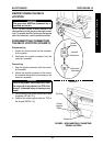
NOTE: The motor connectors are located UN-
DERNEATH the FRONT frame assembly.
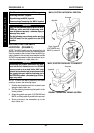
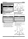
WARNING
When reconnecting the motors, be sure the
motor wires are routed toward the INSIDE
of the wheelchair frame - otherwise, injury
or damage may result.
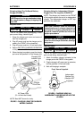
5. Disconnect the LEFT motor connector from
the controller connector.
6. Repeat STEP 5 for the RIGHT motor connector.
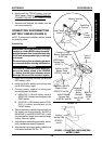
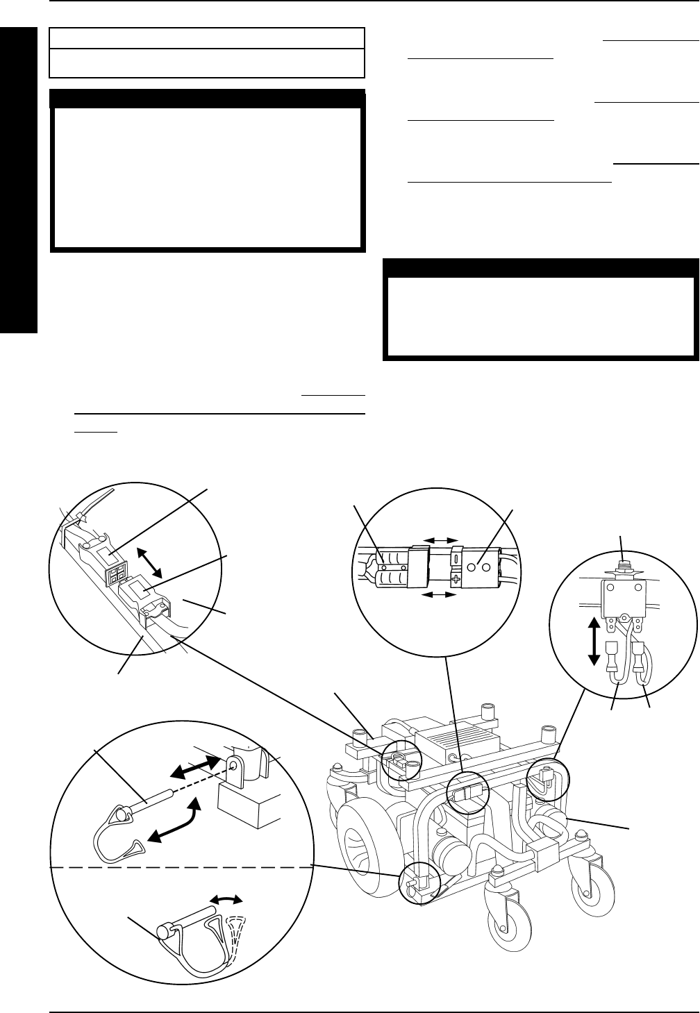
FIGURE 1 - TRANSPORTING THE WHEELCHAIR
Left Motor
Connector
Red
Cable
Black
Cable
Controller
Connector
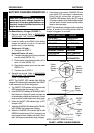
Circuit Breaker
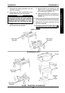
Rear
Frame
Assembly
Front Frame
Assembly
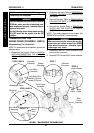
STEP 5 AND 6
STEP 8
STEP 9 AND 10
Bend
Lock
Out
Retaining
Pin Lock
Retaining
Pin
STEP 7
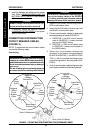
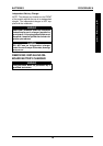
Controller
Connector
Battery
Connector
Left Motor Wire
Routed (Toward
Inside Of Frame)
Wheelchair Frame
DETAIL "A"