


21
INSTALLING.
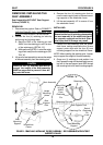
WARNING
Ensure that the four (4) retaining pins securing
the seat assembly to the wheelchair frame
are properly engaged and locked. Other-
wise, injury and/or damage may result.
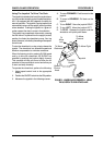
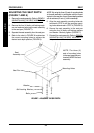
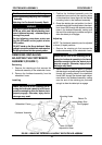
1. Position the seat assembly onto the wheel-
chair frame, making sure that the four (4) seat
support posts align with the four (4) seat
mounting supports on the wheelchair frame.
2. Allow the seat assembly to rest on the four
(4) seat support collars.
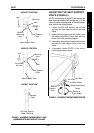
3. Grasp one (1) retaining pin and position it so
that one (1) of the following occurs:
A. Pin passes through the mounting hole di-
rectly below the seat support collars.
B. Pin passes through the mounting holes di-
rectly below the welded collar of the seat
assembly.
NOTE: If the retaining pin will NOT pass through the
desired height mounting hole in the seat support post,
it may be necessary to adjust the seat support post.
Refer to ADJUSTING THE SEAT SUPPORT
POSTS in this procedure of the manual.
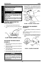
4. Lock the retaining pin by performing the fol-
lowing steps:
A. Swivel the retaining pin lock until it is par-
allel to the retaining pin (DETAIL "A").
B. Bend the end of the retaining pin lock and
position it over the end of the retaining pin
(DETAIL "A").
5. Repeat STEPS 1-4 for the four (4) remaining
seat support posts.
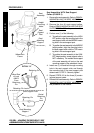
6. Reconnect the joystick. Refer to
CONNECT-
ING/DISCONNECTING THE MKIV JOY-
STICK in PROCEDURE 9 of this manual.
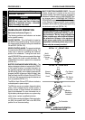
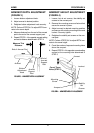
ADJUSTING THE SEAT HEIGHT
Seat Assemblies WITHOUT The Seat
Support Collars (FIGURE 4)
NOTE: The seat can be adjusted to three (3)
height positions.
1. Release the four (4) retaining pins locks by
performing the following steps:
SEAT PROCEDURE 5
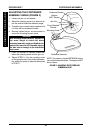
A. Bend the END of the retaining pin lock
AWAY from the retaining pin until it is clear
of the retaining pin (DETAIL "A").
B. While performing STEP A, swivel the retain-
ing pin lock away from the retaining pin (DE-
TAIL "A").
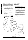
2. Lift up on the seat assembly to remove the weight
of the seat assembly from the retaining pins.
CAUTION
When the four (4) retaining pins are re-
moved the weight of the seat assembly
MUST be supported to prevent it from fall-
ing onto the frame.
3. Remove the four (4) retaining pins that secure
the seat support posts to the wheelchair frame.
4. Adjust the seat assembly to the desired height.
WARNING
Ensure that the four (4) retaining pins securing
the seat assembly to the wheelchair frame
are properly engaged and locked. Other-
wise, injury and/or damage may result.
NOTE: When installing the retaining pins, it neces-
sary to support the weight of the seat assembly.
5. Grasp one (1) retaining pin and positioning it so
that it passes through the seat mounting support
AND through the desired mounting hole in the
seat support post.
6. Lock the retaining pins by performing the fol-
lowing steps:
A. Swivel the retaining pin lock until it is par-
allel to the retaining pin (DETAIL "A").
B. Bend the end of the retaining pin lock and
position it over the end of the retaining pin
(DETAIL "A").
NOTE: If the retaining pin will NOT pass through the
desired height mounting hole in the seat support post,
it may be necessary to adjust the seat support post.
Refer to ADJUSTING THE SEAT SUPPORT
POSTS in this procedure of the manual.
7. Repeat STEP 2 for the seat support post lo-
cated DIAGONALLY across from the seat sup-
port post in STEP 2.
8. Repeat STEPS 3-4 for the two (2) remaining
seat support posts.
S
E
A
T