


SECTION 6—FRONT RIGGINGS
Part No 1122170 41 Formula™ Powered Seating
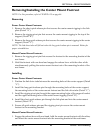
Adjusting Adjustable Angle Flip-Up Footplates
Depth Adjustment
NOTE: For this procedure, refer to FIGURE 6.9 on page 40.
1. Remove the two flat screws, washers and locknuts that secure footplate to the half
clamp.
NOTE: Observe the angle of the footplate for reinstallation.
2. Move footplate to one of four mounting positions.
NOTE: If desired depth is still not obtained, rotate the half clamp on the footplate hinge 180°.
3. Retighten the two flat screws, washers and locknuts.
NOTE: The settings for positioning the footplates on the half-clamps may vary for each footplate.
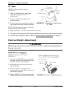
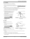
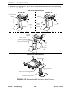
Angle Adjustment
NOTE: For this procedure, refer to FIGURE 6.9 on page 40 and FIGURE 6.10.
1. Loosen, but DO NOT remove, the two
flat screws, washer and locknuts that
secure the footplate to the footplate
hinge (FIGURE 6.9).
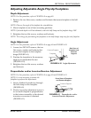
2. Position the footplate to the necessary
angle to accommodate the user
(FIGURE 6.10).
3. Retighten the two flat screws, washers
and locknuts.
FIGURE 6.10 Angle Adjustment
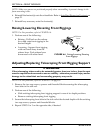
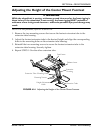
Perpendicular and/or Inversion/Eversion Adjustment
NOTE: For this procedure, refer to FIGURE 6.9 on page 40 and FIGURE 6.11.
NOTE: It is not necessary to remove the
footplate to perform this adjustment.
1. Insert a flathead screwdriver through
the half clamp on the footplate
(FIGURE 6.9).
2. Slowly turn nylon adjustment screw in
or out until footplate is perpendicular
to the footrest assembly or the desired
inversion or eversion is obtained
(FIGURE 6.11).
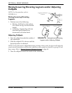
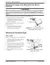
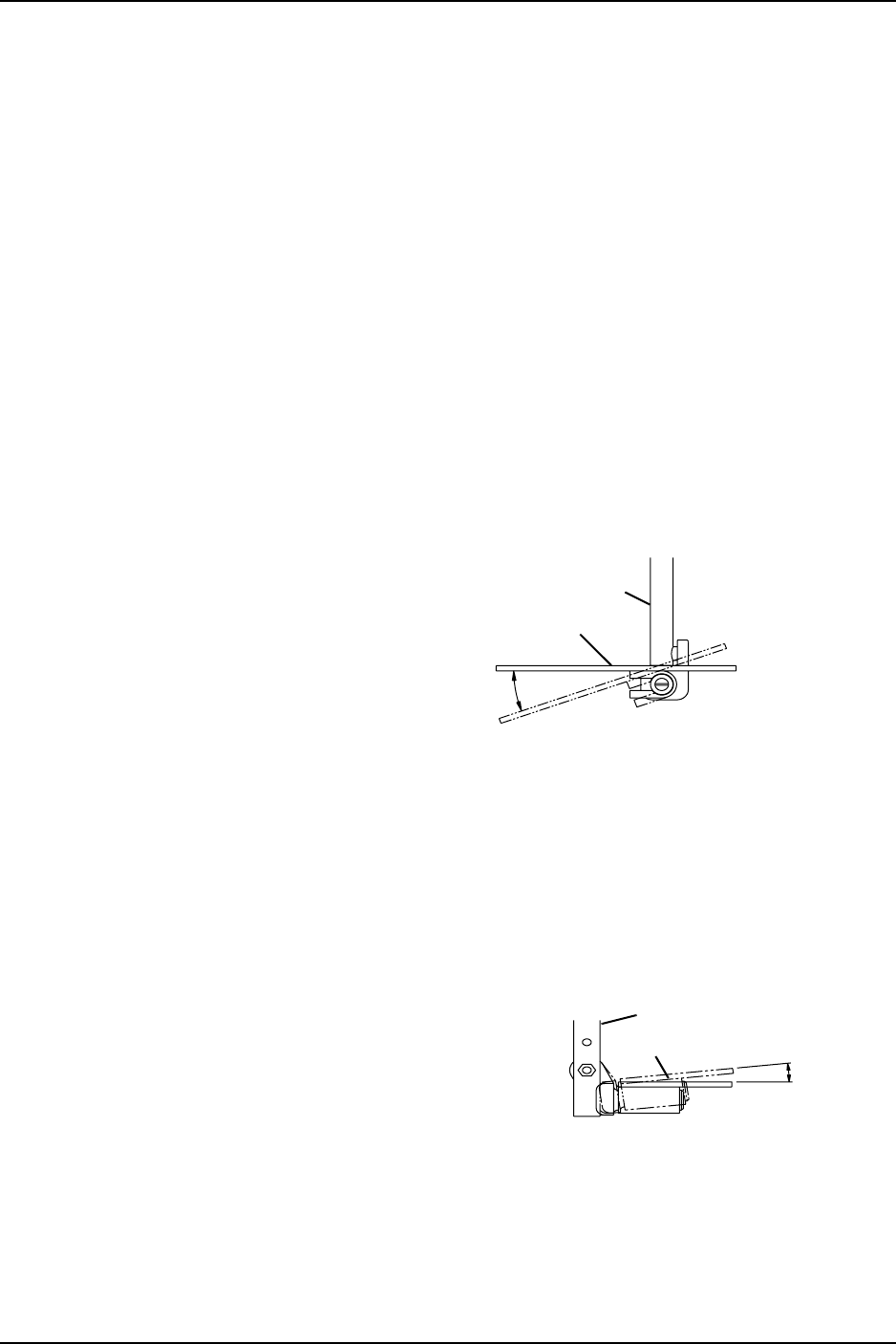
FIGURE 6.11 Perpendicular and/or
Inversion/Eversion Adjustment
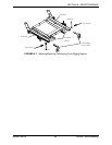
Side View of
Footplate and
Footrest
Support
Footrest Support
Footplate
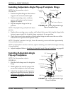
Front View of Footplate
and Footrest Support
Footrest Support
Footplate