


SECTION 6—FRONT RIGGINGS
Formula™ Powered Seating 40 Part No 1122170
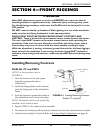
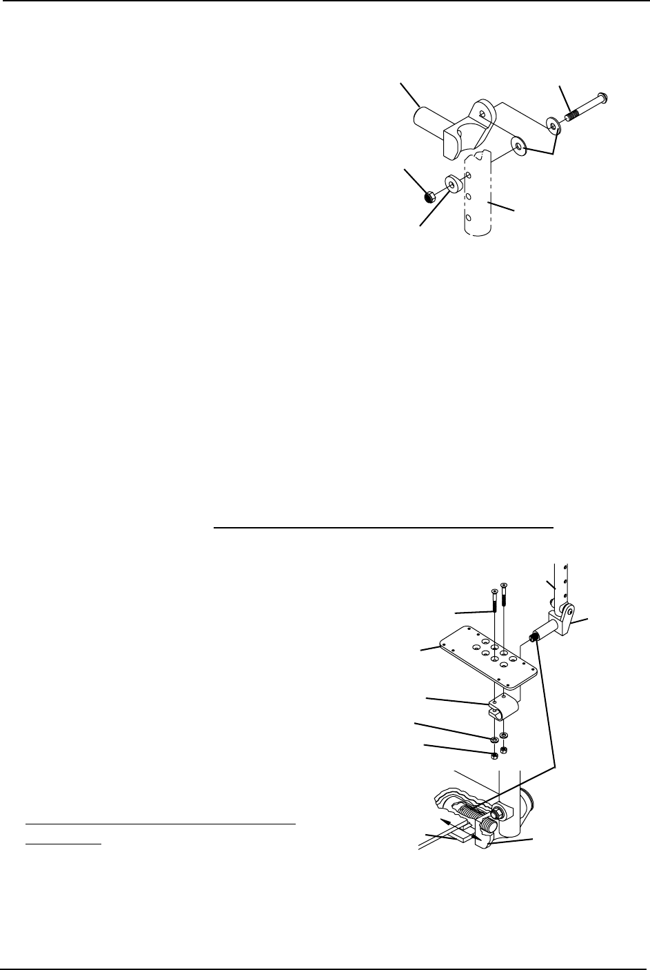
Installing Adjustable Angle Flip-up Footplate Hinge
NOTE: For this procedure, refer to
FIGURE 6.8.
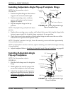
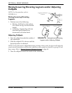
1. Position footplate hinge on the footrest
support tube at the desired height.
2. Position mounting screw, washers,
spacer, and locknut on the footrest
support as shown.
3. Flip the footplate hinge to the up
position.
NOTE: The footplate hinge will fall to the down
position.
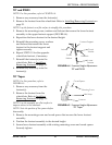
FIGURE 6.8 Installing Adjustable Angle
Flip-up Footplate Hinge
4. Tighten the mounting screw, washer, and locknut that secure the footplate hinge to the
footrest support until the footplate hinge remains in the up position.
5. Check the up and down motion of the footplate hinge to make sure the user of the
wheelchair can operate the footplates easily.
NOTE: If footplate's motion is too tight, loosen the mounting screw and locknut approximately
¼-turn counterclockwise.
NOTE: If the footplate's motion is too loose, tighten mounting screw and locknut approximately
¼-turn clockwise.
6. Adjust footplate. Refer to Installing Adjustable Angle Flip-up Footplates on page 40.
Installing Adjustable Angle
Flip-up Footplates
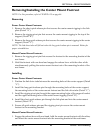
NOTE: For this procedure, refer to
FIGURE 6.9.
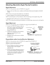
1. Slide the half clamp over the footplate
hinge.
2. Hand tighten the two flat screws that
secure the footplate to the half clamp.
3. Adjust the footplates to the necessary
angle and depth for the user. Refer to
Adjusting Adjustable Angle Flip-Up
Footplates on page 41.
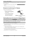
FIGURE 6.9 Installing Adjustable Angle
Flip-up Footplates
Footplate
Hinge
Locknut
Spacer
Footrest Support
Washers
Mounting Screw
Nylon
Adjustment
Screw
Footplat
e
Hinge
90° Footrest Support
Flat Screw
Footplate
Half Clamp
Washer
Locknut
Half Clamp
Footplate Hinge