


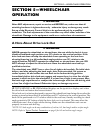
SECTION 5—WHEELCHAIR OPERATION
Formula™ Powered Seating 28 Part No 1122170
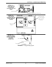
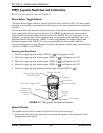
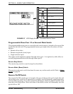
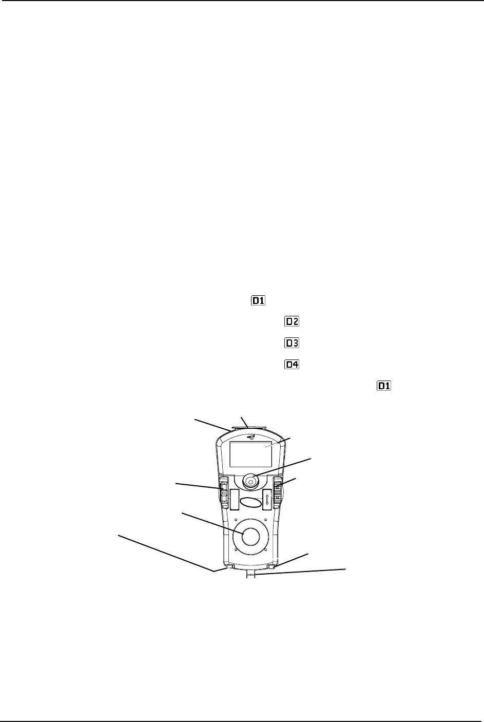
MPJ+ Joystick Switches and Indicators
NOTE: For this procedure, refer to FIGURE 5.3.
Drive Select Toggle Switch
The drive select toggle switch is located on the left side, below the LCD. The drive select
position is momentary, meaning that it will return to the neutral position after a selection
is made.
This switch allows the operator to select the type of operation or performance which best
suits a particular control need or situation. The DRIVE 1 program uses performance
values which are independent of those used for the DRIVE 2 or 3 or 4 program. As an
example, an operator may have a control need for spasticity in the morning and a very
different need in the afternoon. DRIVE 1 can be programmed for higher speeds and
quicker response while DRIVE 2 can be programmed for slower speeds and less
responsiveness or vise versa. The other two drive programs could be indoor and outdoor
versions of DRIVE 1 and DRIVE 2.
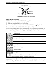
Selecting the Drive Mode
1. Move the toggle up and release. DRIVE 1 ( ) will appear on LCD.
2. Move the toggle up and release again. DRIVE 2 ( ) will appear on LCD.
3. Move the toggle up and release again. DRIVE 3 ( ) will appear on LCD.
4. Move the toggle up and release again. DRIVE 4 ( ) will appear on LCD.
5. Move the toggle up and release one more time to select DRIVE 1 ( ).
FIGURE 5.3 MPJ+ Joystick Switches and Indicators
Speed Control
The speed control knob is located on the side of the joystick housing.
1. Rotate the knob clockwise (forward) to increase the speed of the wheelchair to the
programmed max speed.
Joystick
Remote
On/Off
Input
Programmable
Mono Port 1/2 or
External Mode
Switch
To Controller
Drive Select Toggle Switch
LCD Display
Speed Control Knob
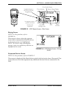
Charger/Programming Input
(Front of Joystick)
Memory Card Slot
Mode Switch