11-3
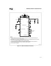
MINIMUM HARDWARE CONSIDERATIONS
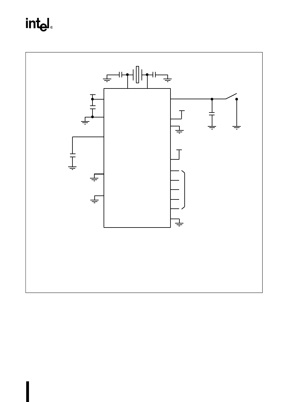
Figure 11-1. Minimum Hardware Connections
ALE
INST
XTAL1XTAL2
V
CC
(Note 2)
0.01 µF
NMI
READY
V
CC
Bus Control
(Note 4)
20 pF 20 pF
(Note 1)
4.7 µF
+
.22 µF
RESET#
BHE#
WR#
RD#
EA#
V
CC
A2415-02
V
SS
RPD
8XC196 Device
V
CC
Notes:
1. See the datasheet for the oscillator frequency range (F
OSC
) and the crystal manufacturer's
datasheet for recommended load capacitors.
2. The number of V
CC
and V
SS
pins varies with package type (see datasheet). Be sure to connect
all V
CC
pins to the supply voltage and all V
SS
pins to ground.
3. Connect the capacitor to RPD when using powerdown mode and the internal oscillator or
phase-locked loop (NU only) circuitry. Otherwise, RPD may float.
4. No connection is required.
(Note 3)
ONCE
(NP Only)
PLLEN1 (NU Only)
PLLEN2 (NU Only)
+


