7-4
8XC196NP, 80C196NU USER’S MANUAL
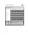
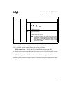
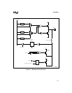
In special-function mode (selected by setting Px_MODE.y), SFDIR and SFDATA are input to the
multiplexers. These signals combine to drive the gates of Q1 and Q2 so that the output is high,
low, or high impedance. Special-function output signals clear SFDIR; special-function input sig-
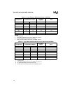
nals set SFDIR. Table 7-5 is a logic table for special-function operation of these ports. Even if a
pin is to be used in special-function mode, you must still initialize the pin as an input or output
by writing to Px_DIR.
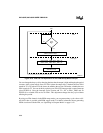
Resistor R1 provides ESD protection for the pin. Input signals are buffered. The ports use
Schmitt-triggered buffers for improved noise immunity. The signals are latched into the Px_PIN
sample latch and output onto the internal bus when the Px_PIN register is read.
The falling edge of RESET# turns on transistor Q3, which remains on for about 300 ns, causing
the pin to change rapidly to its reset state. The active-low level of RESET# turns on transistor Q4,
which weakly holds the pin high. (Q4 can source approximately –10 µA; consult the datasheet
for exact specifications.) Q4 remains on, weakly holding the pin high, until your software writes
to the Px_MODE register.
NOTE
P2.7 is an exception. After reset, P2.7 carries the CLKOUT signal rather than
being held high. When CLKOUT is selected, it is always a complementary
output.


