8XC196NP, 80C196NU USER’S MANUAL
11-2
11.1.1 Unused Inputs
For predictable performance, it is important to tie unused inputs to V
CC
or V
SS
. Otherwise, they
can float to a mid-voltage level and draw excessive current. Unused interrupt inputs may generate
spurious interrupts if left unconnected.
11.1.2 I/O Port Pin Connections
Chapter 7, “I/O Ports,” contains information about initializing and configuring the ports. Table
11-2 lists the sections, with page numbers, that contain the information for each port.
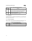
XTAL1 I Input Crystal/Resonator or External Clock Input
Input to the on-chip oscillator, internal phase-locked loop circuitry (80C196NU), and
the internal clock generators. The internal clock generators provide the peripheral
clocks, CPU clock, and CLKOUT signal. When using an external clock source
instead of the on-chip oscillator, connect the clock input to XTAL1. The external
clock signal must meet the V
IH
specification for XTAL1 (see datasheet).
XTAL2 O Inverted Output for the Crystal/Resonator
Output of the on-chip oscillator inverter. Leave XTAL2 floating when the design uses
a external clock source instead of the on-chip oscillator.
Table 11-2. I/O Port Configuration Guide
Port Where to Find Configuration Information
Ports 1–4 “Bidirectional Port Pin Configurations” on page 7-7 and “Bidirectional Port Considerations”
on page 7-9
EPORT “Configuring EPORT Pins” on page 7-17
Table 11-1. Minimum Required Signals (Continued)
Signal
Name
Type Description


