8-5
SERIAL I/O (SIO) PORT
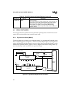
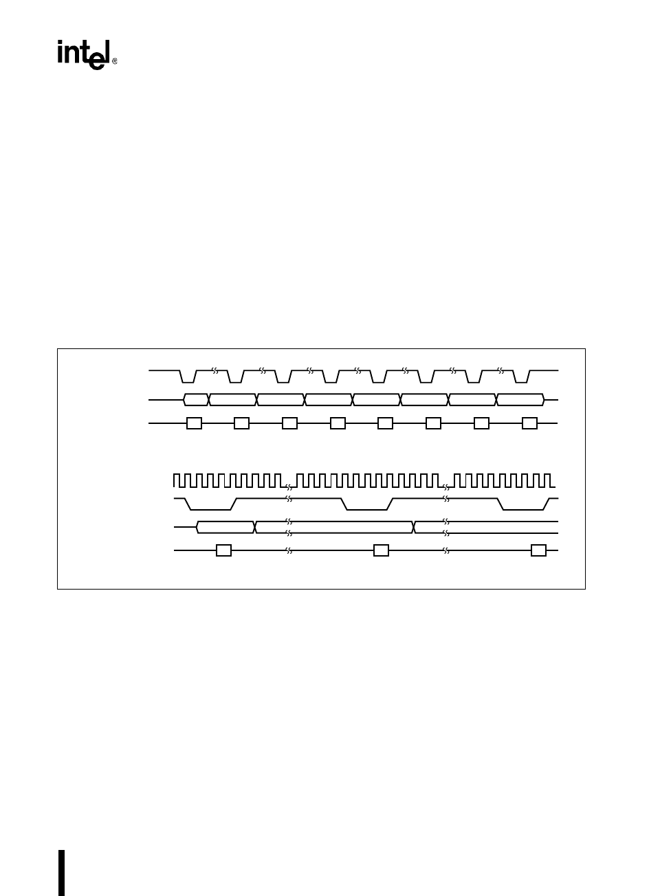
In mode 0, RXD must be enabled for receptions and disabled for transmissions. (See “Program-
ming the Control Register” on page 8-8.) When RXD is enabled, either a rising edge on the RXD
input or clearing the receive interrupt (RI) flag in SP_STATUS starts a reception. When RXD is
disabled, writing to SBUF_TX starts a transmission.
Disabling RXD stops a reception in progress and inhibits further receptions. To avoid a partial or
undesired complete reception, disable RXD before clearing the RI flag in SP_STATUS. This can
be handled in an interrupt environment by using software flags or in straight-line code by using
the interrupt pending register to signal the completion of a reception.
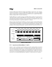
During a reception, the RI flag in SP_STATUS is set after the stop bit is sampled. The RI pending
bit in the interrupt pending register is set immediately before the RI flag is set. During a transmis-
sion, the TI flag is set immediately after the end of the last (eighth) data bit is transmitted. The TI
pending bit in the interrupt pending register is generated when the TI flag in SP_STATUS is set.
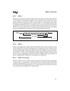
Figure 8-3. Mode 0 Timing
8.3.2 Asynchronous Modes (Modes 1, 2, and 3)
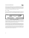
Modes 1, 2, and 3 are full-duplex serial transmit/receive modes, meaning that they can transmit
and receive data simultaneously. Mode 1 is the standard 8-bit, asynchronous mode used for nor-
mal serial communications. Modes 2 and 3 are 9-bit asynchronous modes typically used for in-
terprocessor communications (see “Multiprocessor Communications” on page 8-8). In mode 2,
the serial port sets an interrupt pending bit only if the ninth data bit is set. In mode 3, the serial
port always sets an interrupt pending bit upon completion of a data transmission or reception.
TXD
RXD (OUT)
RXD (IN)
D0
D0
D1 D2 D3 D4 D5 D6 D7
D1 D2 D3 D4 D5 D6 D7
D0
D0
D1 D2
D1
XTAL1
TXD
RXD (OUT)
RXD (IN)
Expanded:
A0109-02


