6-19
STANDARD AND PTS INTERRUPTS
6.6.2 Selecting the PTS Mode
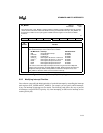
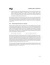
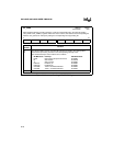
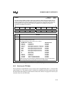
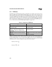
The second byte of each PTSCB is always an 8-bit value called PTSCON. Bits 5–7 select the PTS
mode (Figure 6-11). The function of bits 0–4 differ for each PTS mode. Refer to the sections that
describe each mode in detail to see the function of these bits. Table 6-4 on page 6-10 lists the cycle
execution times for each PTS mode.
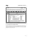
PTSSRV
Address:
Reset State:
0006H
0000H
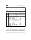
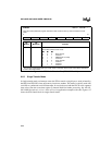
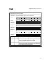
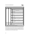
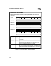
The PTS service (PTSSRV) register is used by the hardware to indicate that the final PTS interrupt
has been serviced by the PTS routine. When PTSCOUNT reaches zero, hardware clears the corre-
sponding PTSSEL bit and sets the PTSSRV bit, which requests the end-of-PTS interrupt. When the
end-of-PTS interrupt is called, hardware clears the PTSSRV bit. The PTSSEL bit must be set
manually to re-enable the PTS channel.
15 8
— EXTINT3 EXTINT2 OVR2_3 OVR0_1 EPA3 EPA2 EPA1
7 0
EPA0 RI TI EXTINT1 EXTINT0 — OVRTM1 OVRTM2
Bit
Number
Function
15, 2 Reserved. These bits are undefined.
14:3
1:0
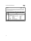
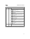
A bit is set by hardware to request an end-of-PTS interrupt for the corresponding interrupt
through its standard interrupt vector.
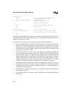
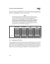
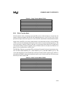
The standard interrupt vector locations are as follows.
Bit Mnemonic Interrupt Standard Vector
EXTINT3 EXTINT3 Pin FF203CH
EXTINT2 EXTINT2 Pin FF203AH
OVR2_3
†
EPA Capture Channel 2 or 3 Overrun FF2038H
OVR0_1
†
EPA Capture Channel 0 or 1 Overrun FF2036H
EPA3 EPA Capture/Compare Channel 3 FF2034H
EPA2 EPA Capture/Compare Channel 2 FF2032H
EPA1 EPA Capture/Compare Channel 1 FF2030H
EPA0 EPA Capture/Compare Channel 0 FF200EH
RI SIO Receive FF200CH
TI SIO Transmit FF200AH
EXTINT1 EXTINT1 pin FF2008H
EXTINT0 EXTINT0 pin FF2006H
OVRTM2 Timer 2 Overflow/Underflow FF2002H
OVRTM1 Timer 1 Overflow/Underflow FF2000H
†
PTS service is not recommended for multiplexed interrupts. This bit is cleared when
both corresponding interrupt pending bits are cleared in EPA_PEND.
Figure 6-10. PTS Service (PTSSRV) Register


