8-12
8XC196NP, 80C196NU USER’S MANUAL
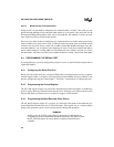
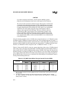
CAUTION
For mode 0 receptions, the BAUD_VALUE must be 0002H or greater.
Otherwise, the resulting data in the receive shift register will be incorrect.
The reason for this restriction is that the receive shift register is clocked from
an internal signal rather than the signal on TXD. Although these two signals
are normally synchronized, the internal signal generates one clock before the
first pulse transmitted by TXD and this first clock signal is not synchronized
with TXD. This clock signal causes the receive shift register to shift in
whatever data is present on the RXD pin. This data is treated as the least-
significant bit (LSB) of the reception. The reception then continues in the
normal synchronous manner, but the data received is shifted left by one bit
because of the false LSB. The seventh data bit transmitted is received as the
most-significant bit (MSB), and the transmitted MSB is never shifted into the
receive shift register.
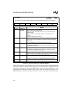
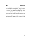
Using the internal peripheral clock at 25 MHz, the maximum baud rate is 4.17 Mbaud for mode
0 receptions and 6.25 Mbaud for mode 0 transmissions. The maximum baud rate for modes 1, 2,
and 3 is 1.56 Mbaud for both receptions and transmissions. For the 80C196NU using the internal
peripheral clock at 50 MHz, the maximum baud rates are doubled: 12.5 Mbaud for mode 0 trans-
missions, 8.33 Mbaud for mode 0 receptions, and 3.13 Mbaud for modes 1, 2, and 3.
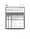
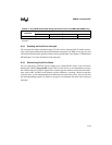
Table 8-3 shows the SP_BAUD values for common baud rates when using a 25 MHz internal
clock. These values also apply to the 80C196NU at 50 MHz with the prescaler enabled. Table 8-3
shows the SP_BAUD value for 9600 baud when using a 50 MHz clock input with the prescaler
disabled. Because of rounding, the BAUD_VALUE formula is not exact and the resulting baud
rate is slightly different than desired. The tables show the percentage of error when using the sam-
ple SP_BAUD values. In most cases, a serial link will work with up to 5.0% difference in the re-
ceiving and transmitting baud rates.
Table 8-3. SP_BAUD Values When Using the Internal Clock at 25 MHz
Baud Rate
SP_BAUD Register Value (Note 1) % Error
Mode 0 Mode 1, 2, 3 Mode 0 Mode 1, 2, 3
9600 8515H 80A2H 0 0.15
4800 8A2BH 8144H 0 0.16
2400 9457H 828AH 0 0
1200 A8AFH 8515H 0 0
300 (Note 2) 9457H (Note 2) 0
NOTES:
1. Bit 15 is always set when the internal peripheral clock is selected as the clock source for the baud-
rate generator.
2. For mode 0 operation at 25 MHz, the minimum baud rate is 381.47 (BAUD_VALUE = 7FFFH).
For mode 0 operation at 300 baud, the maximum internal clock frequency is 19.6608 MHz
(BAUD_VALUE = 7FFFH).


