6-27
STANDARD AND PTS INTERRUPTS
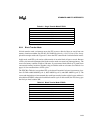
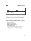
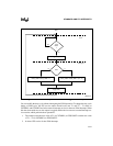
Figure 6-14. A Generic PWM Waveform
The PWM modes do not use a PTSCOUNT register to specify the number of consecutive PTS
cycles. To stop producing the PWM output, first clear the PTSSEL.x bit to disable PTS service
for the interrupt and then use the interrupt service routine to reconfigure the EPA channel.
6.6.5.1 PWM Toggle Mode Example
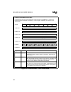
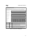
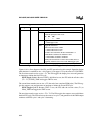
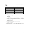
Figure 6-15 shows the PTS control block for PWM toggle mode. To generate a PWM waveform
using PWM toggle mode and EPA0, complete the following procedure. This example uses the
values stored in CSTORE1 and CSTORE2 to control the frequency and duty cycle of a PWM.
1. Disable the interrupts and the PTS. The DI instruction disables all standard interrupts; the
DPTS instruction disables the PTS.
2. Store the on-time value (T1) in CSTORE1.
3. Store the off-time value (T2 – T1) in CSTORE2.
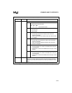
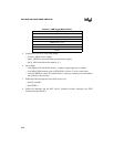
4. Set up the PTSCB as shown in Table 6-8.
— Load PTSCON with 43H (selects PWM toggle mode, initial TBIT value = 1).
— Set up PTSPTR1 to point to EPA0_TIME (the EPA0 event-time register).
— Load PTSCONST1 with the on-time value (T1) from CSTORE1.
— Load PTSCONST2 with the off-time value (T2 – T1) from CSTORE2.
Output Value
1 on off on off
0
0T1 T2
T2 + T1
time
On-time = T1
Off-time = T2 - T1
A0263-02


