9-4
8XC196NP, 80C196NU USER’S MANUAL
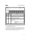
For the 80C196NU, two bits control the PWM output frequency, CON_REG0.0 (CLK0) and
CON_REG0.1 (CLK1). The two bits control the PWM output frequency by enabling or disabling
the divide-by-two or divide-by-four clock prescaler.
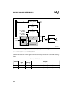
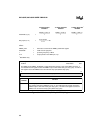
Each control register (PWMx_CONTROL; x = 0, 1, or 2) controls the duty cycle (the pulsewidth
stated as a percentage of the period) of the corresponding PWM output. Each control register con-
tains an 8-bit value that is loaded into a buffer when the 8-bit counter rolls over from FFH to 00H.
The comparators compare the contents of the buffers to the counter value. Since the value written
to the control register is buffered, you can write a new 8-bit value to PWMx_CONTROL at any
time. However, the comparators do not recognize the new value until the counter has expired the
remainder of the current 8-bit count. The new value is used during the next PWM output period.
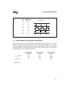
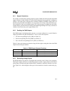
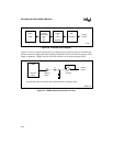
The counter continually increments until it rolls over to 00H, at which time the PWM output is
driven high and the contents of the control registers are loaded into the buffers. The PWM output
remains high until the counter value matches the value in the buffer, at which time the output is
pulled low. When the counter resets again (i.e., when an overflow occurs) the output is switched
high. (Loading PWMx_CONTROL with 00H forces the output to remain low.) Figure 9-3 shows
typical PWM output waveforms.
The PWM can generate a duty cycle ranging in length from 0% to 99.6% of the pulse. To deter-
mine the desired duty cycle measurement, you must apply a multiplier (2, 4, or 8) to the
PWMx_CONTROL value to compensate for the divided input frequency from the divide-by-two
circuitry. (See Chapter 2, “Architectural Overview,” for additional information.)
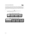
Clearing CON_REG0.0 (CLK0) disables the prescaler, generating a pulse that is 512 state times
in length. With the prescaler disabled, the correct multiplier is 2.
Setting CON_REG0.0 (CLK0) enables the PWM’s divide-by-two clock prescaler, generating a
pulse that is 1,024 state times in length. With the divide-by-two clock prescaler enabled, the cor-
rect multiplier is 4. For example, assume that CLK0 is set and the value you write to the
PWMx_CONTROL register is 19H (25 decimal). To arrive at the appropriate duty cycle, you
must multiply the value stored in PWMx_CONTROL by 4, then divide that result by the total
pulse length (1,024). This calculation results in a duty cycle value of approximately 10% (.0977).
For the 80C196NU, setting CON_REG0.1 (CLK1) enables the divide-by-four clock prescaler,
generating a pulse that is 2,048 state times in length. With the divide-by-four prescaler enabled,
the correct multiplier is 8. (When CON_REG0.1 is set, the divide-by-four clock prescaler is en-
abled and CON_REG0.0 is ignored.)


