ix
CONTENTS
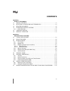
12.3 IDLE MODE................................................................................................................. 12-5
12.4 STANDBY MODE (80C196NU ONLY) ........................................................................ 12-6
12.4.1 Enabling and Disabling Standby Mode ...................................................................12-6
12.4.2 Entering Standby Mode ..........................................................................................12-6
12.4.3 Exiting Standby Mode .............................................................................................12-7
12.5 POWERDOWN MODE................................................................................................ 12-7
12.5.1 Enabling and Disabling Powerdown Mode ..............................................................12-7
12.5.2 Entering Powerdown Mode .....................................................................................12-7
12.5.3 Exiting Powerdown Mode .......................................................................................12-8
12.5.3.1 Generating a Hardware Reset ...........................................................................12-8
12.5.3.2 Asserting an External Interrupt Signal ................................................................12-8
12.5.3.3 Selecting C
1
.....................................................................................................12-10
12.6 ONCE MODE............................................................................................................. 12-12
12.7 RESERVED TEST MODES (80C196NU ONLY)....................................................... 12-12
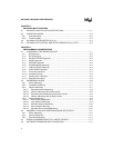
CHAPTER 13
INTERFACING WITH EXTERNAL MEMORY
13.1 INTERNAL AND EXTERNAL ADDRESSES ............................................................... 13-1
13.2 EXTERNAL MEMORY INTERFACE SIGNALS........................................................... 13-2
13.3 THE CHIP-SELECT UNIT............................................................................................ 13-5
13.3.1 Defining Chip-select Address Ranges ....................................................................13-7
13.3.2 Controlling Wait States, Bus Width, and Bus Multiplexing ....................................13-10
13.3.3 Chip-select Unit Initial Conditions .........................................................................13-11
13.3.4 Initializing the Chip-select Registers .....................................................................13-11
13.3.5 Example of a Chip-select Setup ............................................................................13-12
13.4 CHIP CONFIGURATION REGISTERS AND CHIP CONFIGURATION BYTES....... 13-14
13.5 BUS WIDTH AND MULTIPLEXING........................................................................... 13-18
13.5.1 A 16-bit Example System ......................................................................................13-21
13.5.2 16-bit Bus Timings ................................................................................................13-22
13.5.3 8-bit Bus Timings ..................................................................................................13-24
13.5.4 Comparison of Multiplexed and Demultiplexed Buses ..........................................13-26
13.6 WAIT STATES (READY CONTROL)......................................................................... 13-26
13.7 BUS-HOLD PROTOCOL........................................................................................... 13-30
13.7.1 Enabling the Bus-hold Protocol .............................................................................13-32
13.7.2 Disabling the Bus-hold Protocol ............................................................................13-32
13.7.3 Hold Latency .........................................................................................................13-32
13.7.4 Regaining Bus Control ..........................................................................................13-33
13.8 WRITE-CONTROL MODES ...................................................................................... 13-33
13.9 SYSTEM BUS AC TIMING SPECIFICATIONS......................................................... 13-36
13.9.1 Deferred Bus-cycle Mode (80C196NU Only) ........................................................13-40
13.9.2 Explanation of AC Symbols ..................................................................................13-42
13.9.3 AC Timing Definitions ...........................................................................................13-42


