6-7
STANDARD AND PTS INTERRUPTS
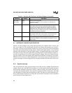
rupt if PTSSEL.5 is set. The interrupt vectors through FF204AH, but the corresponding end-of-
PTS interrupt vectors through FF200AH, the standard SIO transmit interrupt vector. When the
end-of-PTS interrupt vectors to the interrupt service routine, hardware clears the PTSSRV bit. The
end-of-PTS interrupt service routine should reinitialize the PTSCB, if required, and set the appro-
priate PTSSEL bit to re-enable PTS interrupt service.
6.4 INTERRUPT LATENCY
Interrupt latency is the total delay between the time that the interrupt request is generated (not
acknowledged) and the time that the device begins executing either the standard interrupt service
routine or the PTS interrupt service routine. A delay occurs between the time that the interrupt
request is detected and the time that it is acknowledged. An interrupt request is acknowledged
when the current instruction finishes executing. If the interrupt request occurs during one of the
last four state times of the instruction, it may not be acknowledged until after the next instruction
finishes. This additional delay occurs because instructions are prefetched and prepared a few state
times before they are executed. Thus, the maximum delay between interrupt request and ac-
knowledgment is four state times plus the execution time of the next instruction.
When a standard interrupt request is acknowledged, the hardware clears the interrupt pending bit
and forces a call to the address contained in the corresponding interrupt vector. When a PTS in-
terrupt request is acknowledged, the hardware immediately vectors to the PTSCB and begins ex-
ecuting the PTS routine.
6.4.1 Situations that Increase Interrupt Latency
If an interrupt request occurs while any of the following instructions are executing, the interrupt
will not be acknowledged until after the next instruction is executed:
• the signed prefix opcode (FE) for the two-byte, signed multiply and divide instructions
• any of these eight protected instructions: DI, EI, DPTS, EPTS, POPA, POPF, PUSHA,
PUSHF (see Appendix A for descriptions of these instructions)
• any of the read-modify-write instructions: AND, ANDB, OR, ORB, XOR, XORB
Both the unimplemented opcode interrupt and the software trap interrupt prevent other interrupt
requests from being acknowledged until after the next instruction is executed.
Each PTS cycle within a PTS routine cannot be interrupted. A PTS cycle is the entire PTS re-
sponse to a single interrupt request. In block transfer mode, a PTS cycle consists of the transfer
of an entire block of bytes or words. This means a worst-case latency of 500 states if you assume
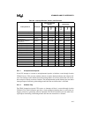
a block transfer of 32 words from one external memory location to another. See Table 6-4 on page
6-10 for PTS cycle execution times.


