


Page 68 AD-4405 Weighing Indicator
18.
18.18.
18.
Relay Output & Control Input (O
Relay Output & Control Input (ORelay Output & Control Input (O
Relay Output & Control Input (OP
PP
P-
--
-05)
05)05)
05)
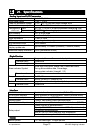
Replacing the RS-232C interface with this option, 3-relay outputs and 3-control inputs
can be used with the RS-232C interface of this option.
RS-232C functions and pin connections are the same as the RS-232C interface
described in “16. RS-232C Interface”.
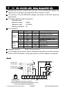
The control inputs can control the indicator from an external terminal just like the front
panel key operations.
Set the external control functions at f13, f14 and f15 of the F-Functions.
When connecting each function pin to the common pin, the indicator makes the action.
Keep a signal width more than 100 ms for the On-time and Off-time.
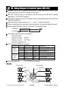
ON(Make)
More than 100 ms More than 100 ms
OFF(Break)
The relays output the result of comparison.
Solid-state-relay
Maximum voltage DC50V
Maximum current DC100mA
Maximum resistance 89
Pin connections (DIN 8pin connector)
Function Pin No. Signal name Direction Description
1 HI Output Relay output HI
6 OK Output Relay output OK
4 LO Output Relay output LO
Relay
output
8 COM(out) - Relay common terminal
3 EXT1 Input Control input 1 (f13)
5 EXT2 Input Control input 2 (f14)
7 EXT3 Input Control input 3 (f15)
Control
input
2 COM(in) - Control input common
Adaptable connector JA-TCP0586 (of accessory)
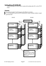
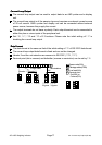
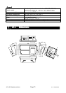
Circuits
CircuitsCircuits
Circuits
HI
O
K
LO
COM
(
out
)
EXT3
EXT2
EXT1
+7 to 9
V
6809
6809
6809
COM
(in)
DIN connector
of OP-05
Control input Relay output
18. Relay Output & Control Input (OP-05)