


Page 66 AD-4405 Weighing Indicator
17.
17.17.
17.
RS
RSRS
RS-
--
-422/RS
422/RS422/RS
422/RS-
--
-485, Relay Output(OP
485, Relay Output(OP485, Relay Output(OP
485, Relay Output(OP-
--
-03
0303
03)
))
)
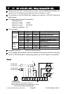
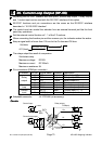
Replacing the RS-232C interface with this option, the RS-422/RS-485 interface can
connect up to 32 indicators and control them from a computer or a PLC.
The functions of the RS-422/RS-485 interface are common to RS-232C except the
signal system.
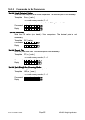
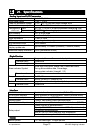
The relays output the result of comparison.
Solid-state-relay
Maximum voltage DC50V
Maximum current DC100mA
Maximum resistance 8Ω
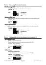
Pin connections
Function Pin No. Signal name Direction Description
1 SDA Output Transmission A terminal
2 SDB Output Transmission B terminal
3 RDA Input Receive A terminal
4 RDB Input Receive B terminal
5 TRM - Terminator resistance (100Ω)
RS-422
RS-485
6 SG - Signal ground
7 HI Output Relay output HI
8 OK Output Relay output OK
9 LO Output Relay output LO
Relay
output
10 COM - Relay output common
Adaptable connector TM-BLA10 (an accessory)
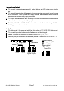
An AC adapter (an accessory) must be connected to the option board when using the
RS-422 or RS-485 interface. If using relay output only, the AC adapter is not required.
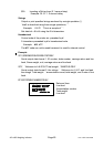
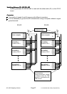
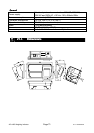
Circuit
CircuitCircuit
Circuit
17. RS-422/RS-485, Relay Output(OP-03)
*+ 1- .1 %1/
Relay Output Terminals
RS-422 Output
RS-485 Output
RS-422 Input
RS-485 Input
5&# 5&$ 4&# 4&$ 64/
RS-422/RS-485 Terminals
5)
DC 7V - 10V
AC adapter Jack
(The AC adapter is an accessory of OP-03)
+
-
Note: Please confirm that the AC adapter type is correc
t
for your local voltage and receptacle type