


8 Digital Communications Interface
8.1 Overview
The communication feature allows an external device, such as a computer, to
communicate with the 1529 to obtain measurement data and control operating
conditions. Communication is accomplished by issuing commands to the 1529
through RS-232 or IEEE-488 communication ports.
8.2 Communications
The thermometer readout is equipped with an RS-232 serial interface, and op
-
tionally a GPIB port. The serial interface allows communications up to dis
-
tances of approximately 50 feet. The serial interface and GPIB port allow the
user to access the functions, parameters, and settings discussed in Section 7,
Menu Functions.
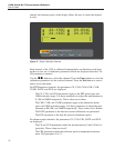
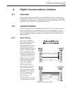
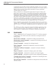
8.2.1 Serial Wiring
The serial communica-
tions cable attaches to the
thermometer readout
through the DB-9 connec-
tor at the back of the in-
strument. Figure 49 shows
the pin-out of this connec-
tor and suggested cable
wiring. This type of cable
is typically referred to as a
“null modem” cable. To
eliminate noise, the serial
cable should be shielded
with low resistance be
-
tween the connector
(DB9) and the shield.
The serial period, baud
rate, linefeed, and echo
are programmable. Refer
to Section 7.5.1.1, Serial
Port, for instructions on
accessing and setting
these parameters.
All commands sent to the
1529 through the serial in
-
77
8 Digital Communications Interface
Overview
Figure 49 Serial Cable Wiring