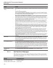
Problem Solution
Incorrect resistance or voltage
reading
While attempting to measure resistance or voltage, the display shows an incorrect value or no value at
all
(..........).
Consider the following possibilities:
Poor or incorrect connection of the probe. A common mistake is to connect the wires of the probe
to the wrong terminals. Check the wiring carefully, especially when using a four-wire PRT (see Section
6.4.1). Make sure the lead wires are fastened down tightly.
Open, shorted, or damaged sensor or lead wires. In the case of resistance sensors check the resis
-
tance across the sensor using a hand-held DMM. Also check the resistance between common pairs of
leads. Check to make sure there is no conductivity between any of the leads and the probe sheath.
Use a good-quality sensor to avoid errors caused by drift, hysteresis, or insulation leakage. In the case
of thermocouples, use a hand-held DMM to check its voltage.
Improper setting for three or four-wire probe. Make sure the correct wiring type is selected Select
-
ing three-wire input while using four-wire probes may cause errors of 0.01 to 0.1 ohms. Selecting
four-wire input while using three-wire probes will result in erratic or out-of-range readings (see Section
7.2.1.1).
Electrical interference. Intense radio-frequency radiation near the 1529 or probes can induce noise
into the measurement circuits resulting in erratic readings. The 1529 is intended to operate in a labora
-
tory environment with limited radio-frequency noise. If interference seems to be a problem you might
try eliminating the source of interference or moving the 1529 to a different location. A well-grounded,
shielded cable should be used for the probe leads.
Stem conduction error. The problem may be that the actual temperature of the sensor is not what
you expect. This is often the result of stem conduction where heat flowing through the stem of the
probe to ambient affects the temperature of the probe. It is very important that probes be inserted to an
adequate depth into the material being measured. Measuring temperature using a surface sensor can
be especially difficult as the sensor is directly exposed to ambient.
Wrong calibration parameters. The problem may be that the calibration parameters for the 1529 are
invalid. Check the parameters currently stored in the unit against those listed on the 1529 Report of
Calibration.
Blank screen
The screen lights up when the 1529 is switched on but the screen appears blank. This problem
can be caused by improper adjustment of the contrast. After the power is switched on allow the 1529
at least one minute to complete its self-test and power on sequence. Then, try to adjust the contrast
using the contrast buttons.
Error message at power up
The 1529 reports an error during the power up self-test. On power up the 1529 performs a series of
self-tests to check the operation of all its components and each of the modules. The results of the
self-tests are reported on the screen. Normally, all tests report ‘OK’. Below is a table of error messages
and recommended actions to correct the error. Often these errors can be corrected by completing the
actions listed. A failure of one or more component causes error messages to be reported. Component
failures generally require a qualified factory technician to replace the faulty component. Contact an Au
-
thorized Service Center (see Section 1.3).
Temperature not
updating
The 1529 measure period may be set to a long interval. Check the measure period.
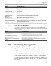
11.1.1 Self-Test Error Messages
The following messages may appear during the self-test. If the recommended
action fails to correct the error, contact an Authorized Service Center (see Sec
-
tion 1.3) for assistance.
Message Recommended Action
SYSTEMS: INVALID TIME Set the date and time.
SYSTEMS: SERIAL PORT FAILURE Cycle the power.
1529 Chub-E4 Thermometer Readout
User’s Guide
136


