


Instruction Manual
IM-106-910Xi, Original Issue
November 2010
6-11
Xi Advanced Electronics
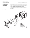
Power Supply Board
Replacement
Use the procedure that follows to replace the Power Supply board in the Xi.
Use this procedure to replace an original Linear Power Supply board or the
current configuration Switching Power Supply board.
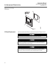
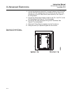
1. Loosen the four screws securing the Xi cover. The screws are captive
and do not need to be completely removed.
2. Swing the Xi cover down to expose the inner components.
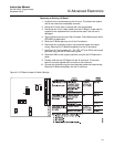
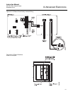
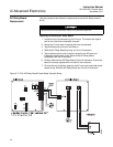
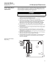
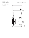
3. Refer to the wiring diagram in Figure 6-9. Unplug the AC input wiring
plug from the Power Supply board. A new plug is supplied in the
replacement kit and should be used if the existing plug is damaged.
4. Disconnect the 14-pin ribbon cable from the Power Supply board.
5. Remove the two long screws that secure the bracket (9, Figure 6-1) to
the Xi enclosure.
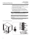
6. Hold the AC input wiring to the right and slide the Power Supply board
out of the Xi enclosure.
7. Install the new mounting bracket (9, Figure 6-1) on the new Power
Supply board (10, Figure 6-1). A new bracket and mounting screws are
provided in the replacement kit.
8. Slide the Power Supply board into the mating slots in the Xi Enclosure.
Make sure the board is correctly aligned in the slots.
9. Install and tighten the bracket mounting screws. Two new screws are
provided in the replacement kit and should be used if the existing
screws are damaged.
Figure 6-9. Power Supply
Board Wiring
Disconnect and lock out power before working on any electrical components.