


Xi Advanced Electronics
2-8
Instruction Manual
IM-106-910Xi, Original Issue
November 2010
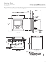
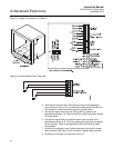
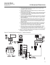
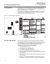
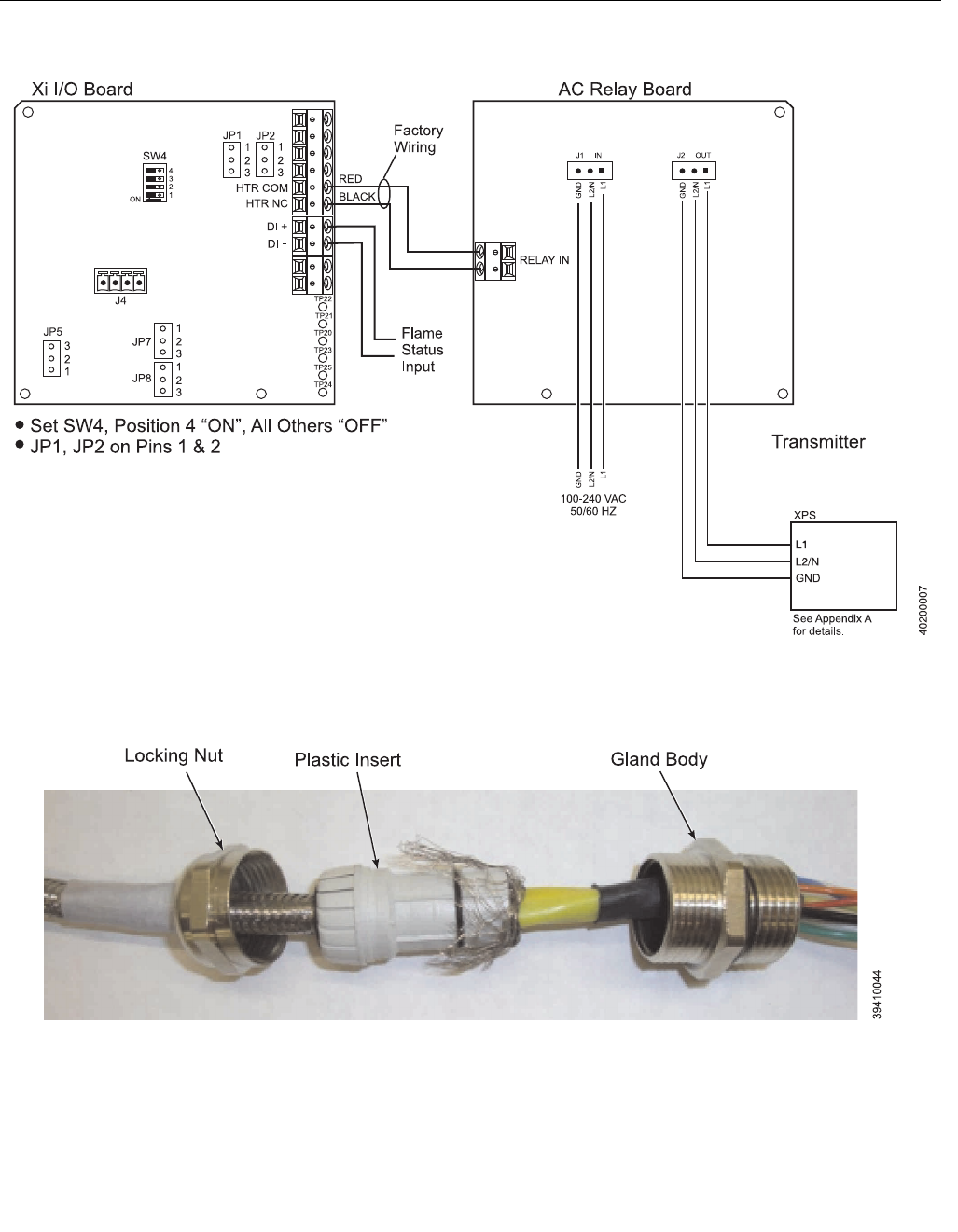
Figure 2-7. Flame Safety Interlock - Wiring Diagram
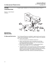
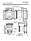
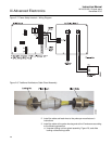
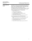
Figure 2-8. Traditional Architecture Cable Gland Assembly
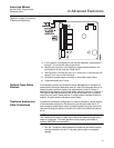
2. Install the cable and lead wires to the probe per manufacturer’s
instructions.
3. Install the cable at the probe housing and at the Xi enclosure according
to the following procedure:
a. Unscrew locking nut from gland assembly, Figure 2-8, and slide
locking nut back along cable.