


Xi Advanced Electronics
4-8
Instruction Manual
IM-106-910Xi, Original Issue
November 2010
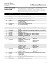
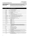
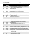
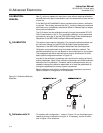
PROBE PARAMETER
DESCRIPTIONS
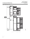
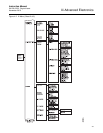
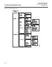
Among the parameters available through the Xi and 375/475 Field
Communicator menus are a number of "Probe Parameters". The probe
parameters define variables that configure a specific probe in the transmitter
system. Probe parameters are described in the following table.
TX I/O
PARAMETER
NAME UNITS PARAMETER DESCRIPTION
Y Y O2 % Current oxygen concentration value (O2%). The value should reflect the last good O2 value if it
is in the "Lock" state during calibration.
Y Y O2 Temp degC Current O2 sensor temperature.
Y Y CJC Temp degC Current cold junction temperature.
N Y Elec Temp degC Current electronic temperature measured at the I/O board.
Y Y O2 Cell mV Raw mV value for ZrO
2
sensor.
N Y TC Volt mV O2 T/C voltage.
Y Y Cell Imp Ohm Cell impedance/sensor resistance measured.
Y Y Htr Volt Volt Heater voltage.
Y Y CPU Volt Volt Transmitter CPU voltage.
Y Y O2 AO mA Analog output value represents the O2 concentration measurement.
N Y O2 AO% % O2 analog output percentage for O2 AO.
Y Y O2 Temp Max degC This is the highest O2 sensor temperature reached since last reset.
Y Y CJC Temp Max degC This is the highest temperature reached at the cold junction since last reset.
N Y Elec Temp Max degC This is the highest temperature reached at the I/O board since last reset.
Y Y Htr Volt Max degC This is the highest heater voltage reached since last reset.
Y Y Htr Duty Cycle -- O2 heater duty cycle. Value between 0 and 1.
Y Y PID SP degC PID temperature set point.
Y Y Htr Ramp Rate degC/s Heater ramp rate calculated in degree C per second.
N Y Flame Stat In -- Flame status input state.
(OFF/ON)
N Y SPS/IMPS In -- SPS/IMPS input state.
(OFF/ON)
N Y SPS/IMPS Out -- SPS/IMPS output state.
(OFF/ON)
N Y Alm Relay 1 Out -- Alarm Relay 1 output state.
(OFF/ON)
N Y Alm Relay 2 Out -- Alarm Relay 2 output state.
(OFF/ON)
Y Y OP Mode -- Device operating mode:
PO=Power up; WU=Warm Up (analog output is railed); NM=Normal operation;
CA=Calibrating (analog output can be tracking or locked at last good value based on
"AO Tracks" configuration); AL=Alarm detected (recoverable); SF=Alarm detected
(non-recoverable)
Y Y Tag -- Device tag.
Y Y Device ID -- Unique Device ID number. (HART)
Y Y PV is -- Primary variable assignment. (HART)
Y Y SY is -- Secondary variable assignment. (HART)
Y Y TY is -- Third variable assignment. (HART)
Y Y QV is -- Fourth variable assignment. (HART)
Y Y Cal Slope mV/Dec Current calibration slope. This is the slope value that was calculated as a result of the last
successful calibration.
Y Y Cal Const mV Current calibration constant. This is the constant value that was calculated as a result of the last
successful calibration. It is valid between -4mV and +10mV.
Y Y Cal Imp Ohm Cell Impedance. This is the sensor resistance that was calculated as a result of the last
successful calibration.
N Y Prev Slope mV/Dec Previous calibration slope. There are ten calibration results. 1 is the most recent and 10 is the
least recent calibration slope.
N Y Prev Const mV Previous calibration constant. There are ten calibration results. 1 is the most recent and 10 is
the least recent calibration constant.