


Instruction Manual
IM-106-910Xi, Original Issue
November 2010
5-3
Xi Advanced Electronics
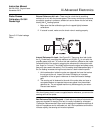
Electrical Noise
The Xi has been designed to operate in the type of environment normally
found in a boiler room or control room. Noise suppression circuits are
employed on all field terminations and main inputs. When fault finding,
evaluate the electrical noise being generated in the immediate circuitry of a
faulty system. Ensure all cable shields are connected to earth.
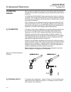
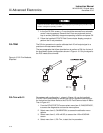
Electrostatic Discharge
Electrostatic discharge can damage the ICs used in the electronics. Before
removing or handling the circuit boards, ensure you are at ground potential.
ALARM INDICATIONS
The first indication of a problem at the O
2
measuring system usually comes
from the operators running the process. Critical alarms that render the O
2
measurement unusable will force the 4-20 mA analog output signal represent-
ing O
2
to go to a default condition, as follows:
NOTE
To ensure correct operation you should make sure that the Digital Control
System is configured to interpret these signal levels correctly.
Once an alarm condition is identified, the Xi offers a number of diagnostics to
interpret the specific alarm.
Alarm indications are available via the Xi or the 375/475 Field Communicator
and Rosemount Analytical's Asset Management software. When the error is
corrected and/or power is cycled, the diagnostic alarms will clear or the next
error on the priority list will appear.
IDENTIFYING AND
CORRECTING FAULT
INDICATIONS
There are two types of alarms; recoverable and non recoverable. If an
existing alarm is recoverable, the alarm-active indication will disappear when
the alarm condition no longer exists. If an alarm is not recoverable, the alarm
indication will continue to be displayed after the cause of the alarm condition
is corrected. AC power to the Xi must be cycled to clear a non-recoverable
alarm.
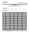
Alarm messages are displayed on the Xi display window when the alarm
status display is accessed via the Xi menu. A listing of the alarm/fault
messages and the related fault status descriptions are shown in Table 5-1.
Fault conditions that give no fault indication and that allow the probe to pass
calibration are listed and discussed after Table 5-1.
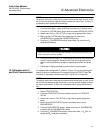
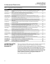
4-20 mA Signal
Alarm Level
Transmitter Condition
0 mA Transmitter unpowered, or completely failed
3.5 mA Critical Alarm - transmitter reading unusable (factory default)
3.8 mA
Reading Under Range
(Example - user sets range to 2-10%. Current reading is 1.9%)
4 to 20 mA Normal Operation
20.5 mA Reading Over Range (Example - range is 0-10%. Current reading is 12%)
>21 mA
Critical Alarm - transmitter reading is unusable (user can choose this alarm
level instead of the factory default level of 3.5 to 3.6 mA)