


Xi Advanced Electronics
6-10
Instruction Manual
IM-106-910Xi, Original Issue
November 2010
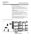
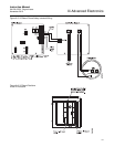
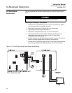
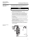
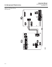
8. Connect two wires approximately 6" long each between the "HTR COM"
and the "HTR NC" connections on the I/O Board and the "RELAY IN"
connections on the AC Relay Board; observe polarity. See Figure 6-7
for wiring details.
9. Connect the flame status indicator contact to the "DI+" and "DI-" on the
AC Relay Board. See Figure 6-7 for wiring details.
10. Connect the AC input and output wiring to the Transmitter. See
Figure 6-7 for wiring details.
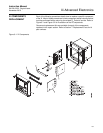
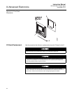
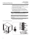
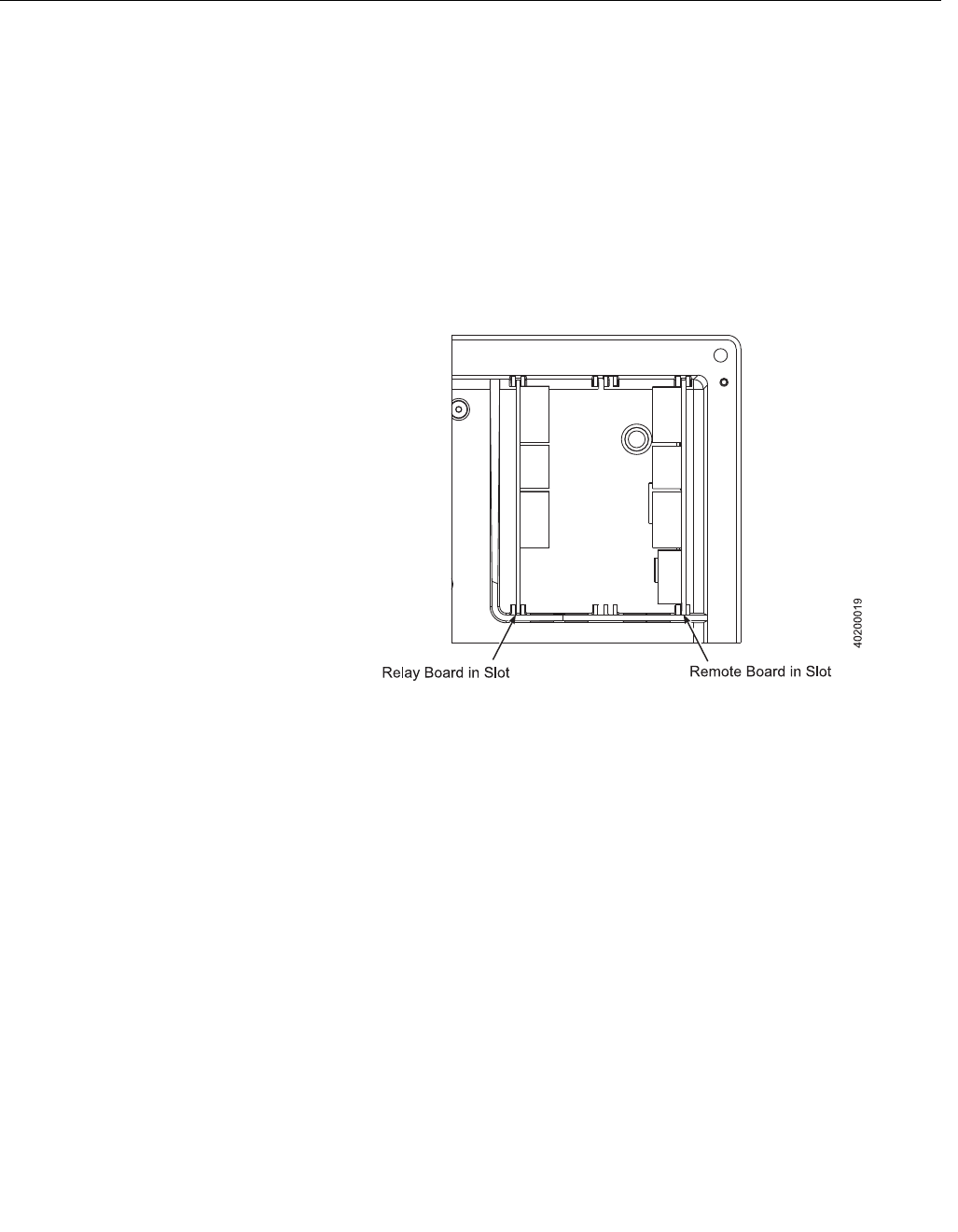
11. Slide the AC Relay Board completely into the Xi enclosure.
12. Swing the cover up in place and tighten the four screws.
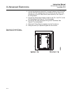
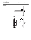
Figure 6-8. I/O and AC Relay
Board Position in Xi Enclosure