


Xi Advanced Electronics
2-6
Instruction Manual
IM-106-910Xi, Original Issue
November 2010
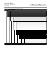
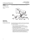
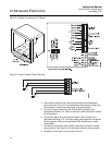
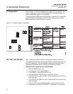
Figure 2-4. Signal Connections at I/O Board
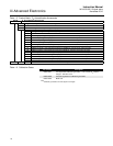
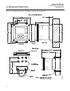
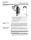
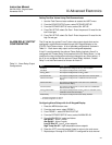
Figure 2-5. Alarm Indicator Relay Terminals
4. Terminate the shield of the 4-20 mA signal wires at the designated
ground terminal of the Xi. Do not allow bare shield wires to contact the
circuit boards. Insulate the shield wires prior to termination.
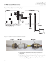
5. Connect the signal wires from the SPS or IMPS (if used) to the
applicable terminals of J3. Refer to the SPS or IMPS instruction manual
for wiring details.
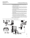
6. Connect the signal wires for the flame status input (if used) to the
applicable terminals of J2. The flame status sensing device is supplied
by the customer. Refer to the applicable OEM documents for signal
wiring details.
7. Connect the customer’s alarm indicator devices to the alarm indicator
relay terminals. See Figure 2-5 for the alarm indicator relay terminals.
8. Reinstall the I/O board in the card rack of the Xi.