


Instruction Manual
IM-106-910Xi, Original Issue
November 2010
6-5
Xi Advanced Electronics
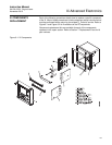
Replacing an Existing I/O Board
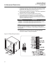
1. Loosen the four screws securing the Xi cover. The screws are captive
and do not need to be completely removed.
2. Swing the Xi cover down to expose the inner components.
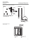
3. Disconnect the 10-pin ribbon cable from the I/O Board. A new cable is
supplied in the replacement kit and should be used if the old one is
damaged.
4. Tag and disconnect wiring for Alarm Outputs, Flame Status Input and/or
SPS/IMPS as applicable.
5. Slide the I/O Board part way out of the Xi enclosure.
6. Disconnect the 4-position plug for the transmitter probe and output
wiring. Remove the I/O Board completely from the Xi enclosure.
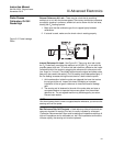
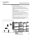
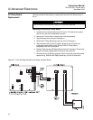
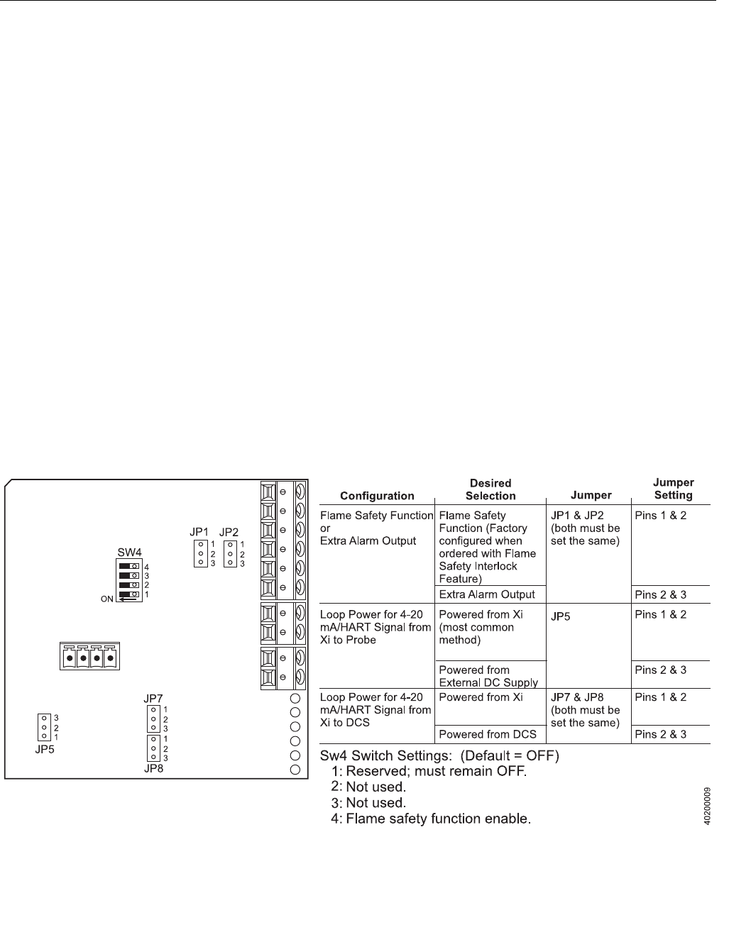
7. See Figure 6-3. Set jumpers JP1, JP2, JP5, JP7 and JP8 to their proper
positions using the old I/O Board as a guide.
8. Set switch SW4 to their proper positions using the old I/O Board as a
guide.
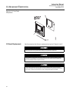
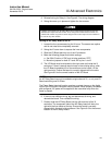
9. Partially slide the new I/O Board into the Xi enclosure. Ensure the
board is correctly aligned within the slots in the enclosure.
10. Connect the 4-position plug for the transmitter probe and output wiring.
Slide the I/O Board completely into the Xi enclosure.
Figure 6-3. I/O Board Jumper & Switch Settings