


Instruction Manual
IM-106-910Xi, Original Issue
November 2010
2-9
Xi Advanced Electronics
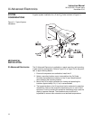
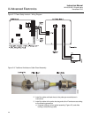
b. Pull the gland body away from the plastic insert. Use care not to
damage the cable shield braid.
c. Insert the cable wires into the proper entry port in either the probe
housing or the Xi enclosure.
d. At the probe housing, apply Teflon tape or similar sealing compound
to the tapered pipe threads. Thread the gland body into the probe
housing until properly seated.
e. At the Xi enclosure, insert the gland body into the left front cable port
from the inside of the enclosure. Use the rubber O-ring provided to
seal the cable port.
f. Ensure the cable shield braid is evenly formed over the gray insert.
When properly formed, the braid should be evenly spaced around
the circumference of the insert and not extend beyond the narrow
diameter portion.
g. Carefully press the gray insert into the gland body. The grooves on
the insert should align with similar grooves inside the gland body.
Press the insert in until it bottoms out in the gland body.
h. Slide the locking nut up and thread it onto the gland body. Tighten
the locking nut so the rubber grommet inside the plastic insert
compresses against the cable wall to provide an environmental seal.
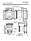
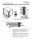
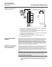
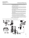
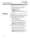
4. At the Xi, connect the cable leads to the connectors on the transmitter
I/O board as indicated in Figure 2-9.
Figure 2-9. Transmitter Board Connections at Xi - Traditional Architecture