


Instruction Manual
IM-106-910Xi, Original Issue
November 2010
2-7
Xi Advanced Electronics
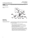
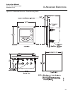
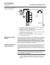
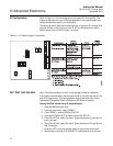
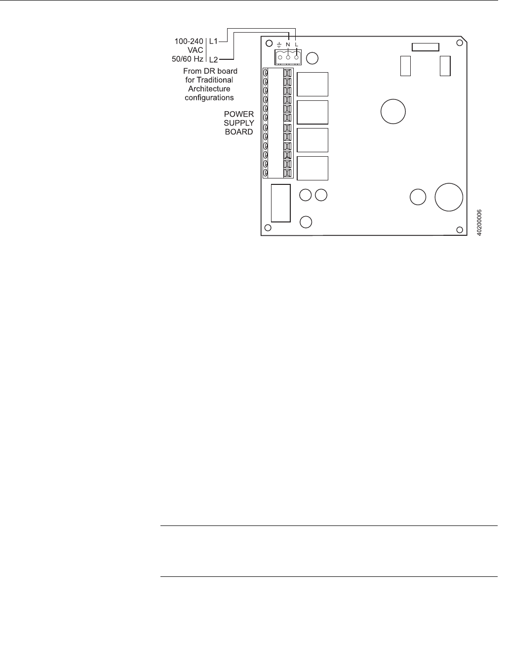
Figure 2-6. Power Connections -
Xi Advanced Electronics
9. If your system is configured for two channel operation, repeat steps 2
through 7 to connect the other signal wires.
10. Remove the connector from the power supply board located on the
left-hand side of the card rack inside the Xi.
11. See Figure 2-6. Connect the line, or L1 wire to the L1 terminal and the
neutral, or L2 wire, to the N terminal.
12. Reinstall the power supply connector in the power supply board.
13. Close and fasten the Xi cover.
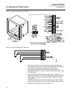
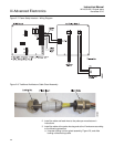
Optional Flame Safety
Interlock
A flame safety interlock by Emerson Process Management is available for
heater power disconnect whenever there is a loss of the process flame or a
heater runaway condition (heater over-temperature) in the O
2
Probe. A
simplified wiring diagram for the flame safety interlock is shown in Figure 2-7.
This input is internally powered by the Xi and is actuated via a dry contact
output from the user’s flame scanner. A closed contact indicates a flame is
present. An open contact indicates a loss of flame.
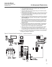
Traditional Architecture
Cable Connections
A traditional architecture configuration is used to provide for remote location
of the transmitter electronics. All electronics are housed inside the Xi. A
multi-conductor power/signal cable connects between the probe and the Xi.
Use the following procedure to connect the traditional architecture probe to
the Xi.
NOTE
The Traditional Architecture cable is provided at the specified length and is
ready for installation. The cable glands must be properly terminated to
maintain EMC/EMI noise protection.
1. Run the 7-conductor cable between the traditional architecture probe
and the installation site for Xi. Use new cable conduit or trough as
needed.