


MODEL DO-03/04 SECTION 10.0
TROUBLESHOOTING
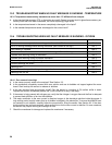
10.5 TROUBLESHOOTING NOT RELATED TO MEASUREMENT PROBLEMS
Problem Action
Display segments missing Replace display board
Alarm relays are chattering 1. Check alarm setpoints.
2. Increase hysteresis time delay settings (see Section 5.6)
Incorrect current output 1. Verify that output load is less than 600 Ω.
2. For minor errors, trim outputs (see Section 8.0)
3. Replace power supply board
Display too light or too dark Change contrast (see Section 5.4)
“Level 1, 2 or 3 security: Lock” shown in display Controller has password protection (see Section 5.11)
“Hold mode activated” showing in display Controller is in hold (see Section 5.5, steps 8 and 9)
“Simulating output 1 or 2” showing in display Controller is simulating outputs (see Section 5.3)
“Simulating alarm 1, 2, 3 or 4” showing in display Controller is simulating alarms (see Section 5.3)
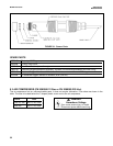
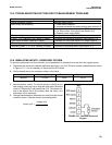
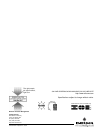
10.6 SIMULATING INPUTS - DISSOLVED OXYGEN
To check the performance of the controller, use a decade box to simulate the current from the oxygen sensor.
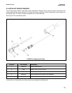
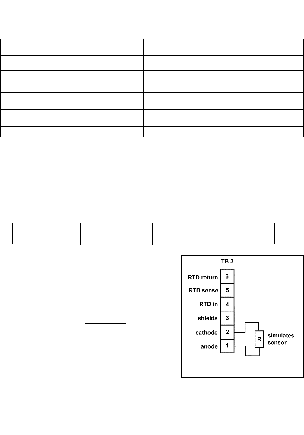
A. Disconnect the anode and cathode leads from terminals 1 and 2 on TB3 and connect a decade box as shown
in Figure 10-1. It is not necessary to disconnect the RTD leads.
B. Set the decade box to the resistance shown in the table.
C. Note the sensor current. To view the sensor current from the
main display, press any key to enter the main menu. Move the
cursor to "Diagnostics" and press Enter (F4). The sensor cur-
rent is the second line in the display. Note the units: μAis
microamps, nA is nanoamps.
D. Change the decade box resistance and verify that the correct
current is shown. Calculate current from the equation:
current (μA) =
Sensor Polarizing Voltage Resistance Expected current
499ADO -675 mV 34 kΩ 20 μA
voltage (mV)
resistance (kΩ)
FIGURE 10-1. Simulate Dissolved
Oxygen
59