


12
MODEL DO-03/04 SECTION 3.0
WIRING
SECTION 3.0
WIRING
3.1 GENERAL
WARNING
Electrical installation must conform to the National Electrical Code, all state and local codes, and all plant
codes and standards for electrical equipment. Electrical installation and wiring must be done by qualified
personnel.
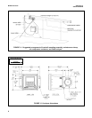
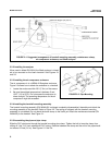
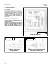
The five holes in the bottom of the Model 54eA enclosure accept 1/2-in. (PG-13.5) strain relief connectors or con-
duit fittings. The rear openings are for power and alarm relay wiring. The left front opening is for sensor wiring and
the right front opening is for analog output wiring. Seal unused openings with conduit plugs.
3.2 POWER, ALARM, AND OUTPUT WIRING
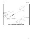
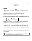
Figure 3-1 shows the power, relay, and current output terminals. For access to the terminals, loosen the screw hold-
ing the protective cover in place and remove the cover. Make power and alarm connections on TB3. Make analog
output wiring connections on TB2.
DANGER
Live voltages may be present.
Will cause severe injury or death.
Alarm contacts are dry (i.e., not powered) and are normally open. Refer to Section 1.0 for relay specifications.
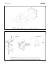
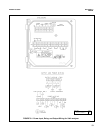
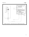
Refer to Figure 3-2 or 3-3 for details on how to wire the Model ABSH (air blast system) to the 54eA analyzer. Figure
3-2 is for Model DO-03 (115 Vac 60 Hz). Figure 3-3 is for Model DO-04 (220 Vac 50 Hz).
NOTE
The 54eA analyzer has four alarm relays. Relays 1, 2, or 3 are normally open (NO) and can be used to
operate the air blast cleaner. The wiring diagrams show alarm relay 3 being used. The relay used for the
air blast cleaner MUST be configured as an interval timer. See Section 5.6 for programming details.
For best EMI/RFI protection, shield the output cable and enclose it in an earth-grounded, rigid, metal conduit.
Connect the outer shield of the output cable to the earth ground connection on TB2 (see Figure 3-1).
Keep sensor and output signal wiring separate from power wiring. Do no run sensor and power cables in the same
conduit or close together in a cable tray.
AC wiring must be 14 gauge or greater. Be sure to connect earth ground from the power cable to the nearby
ground lug. A good earth ground is necessary for proper operation of the analyzer. Provide a switch or breaker to
disconnect the analyzer from the main power supply. Install the switch or breaker near the analyzer and label it as
the disconnecting device.
WARNING: RISK OF ELECTRICAL SHOCK
AC connections and grounding must comply with UL 508 or local electrical code. DO NOT apply
power to the analyzer until all electrical connections are verified and secure.