


iii
MODEL DO-03/04 TABLE OF CONTENTS
LIST OF FIGURES
Section Title Page
1-1 Suggested Arrangement of Handrail Mounting Assembly, Maintenance Clamp,....
Air Compressor Enclosure, and 54eA Analyzer ...................................................... 4
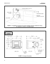
1-2 Analyzer Dimensions............................................................................................... 4
1-3 Enclosure Dimensions............................................................................................. 5
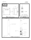
1-4 Standard Sensor with Integral Cable....................................................................... 5
1-5 Air Blast Washer Head ............................................................................................ 5
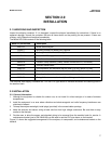
2-1 Suggested Arrangement of Handrail Mounting Assembly, Maintenance Clamp,....
Air Compressor Enclosure, and 54eA Analyzer ...................................................... 8
2-2 Pipe Mounting.......................................................................................................... 8
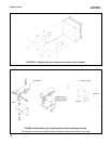
2-3 Attaching the Air Compressor Enclosure to the Handrail........................................ 10
2-4 Assembling and Attaching the Handrail Mounting Assembly .................................. 10
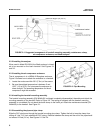
2-5 Installing the Sensor in the Washer Head Assembly .............................................. 11
3-1 Power Input, Relay, and Output Wiring for 54eA Analyzer...................................... 13
3-2 Model DO-03 — Wiring Air Blast Compressor to Model 54eA Analyzer 115 Vac.. 14
3-3 Model DO-04 — Wiring Air Blast Compressor to Model 54eA Analyzer 230 Vac.. 15
3-4 Wiring Label............................................................................................................. 16
3-5 Oxygen Sensor with Standard Cable ...................................................................... 16
3-6 Oxygen Sensor with Optimum EMI/RFI Cable or Variopol Cable........................... 16
4-1 Main Display Screen................................................................................................ 17
5-1 Menu Tree for the 54eA Analyzer............................................................................ 18
5-2 Low Alarm................................................................................................................ 32
5-3 High Alarm ............................................................................................................... 32
5-4 Interval Timer .......................................................................................................... 34
7-1 Sensor Current as a Function of Dissolved Oxygen Concentration ....................... 43
9-1 Sensor Parts............................................................................................................ 52
9-2 Replacement Parts .................................................................................................. 53
10-1 Simulate Dissolved Oxygen..................................................................................... 59
10-2 Three-Wire RTD Configuration................................................................................ 60
10-3 Simulating RTD Inputs............................................................................................. 60