


MODEL DO-03/04 SECTION 4.0
DISPLAY AND OPERATION
SECTION 4.0
DISPLAY AND OPERATION
4.1 DISPLAY
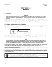
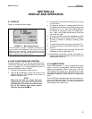
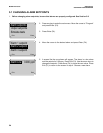
Figure 4-1 shows the main display.
4.2 KEY FUNCTIONS AND CONTROL
The keys labeled F1, F2, F3, and F4 are multi-function.
The function appears in the main display just above the
key. For example, F1 is usually labeled Exit and F4
may be labeled Edit, Save, or Enter.
1. To enter the main menu, press any key.
2. Use the and keys to move the cursor to the
desired sub-menu. The position of the cursor is
shown in reverse video.
NOTE
When the last item of a menu has been
reached, the cursor will be on the third line
of the display. If the cursor is on the second
line of the display more items remain.
Continue pressing the
key.
3. Press Enter (F4) to access a sub-menu or an item
in a sub-menu.
4. To change a number or a setting press Edit (F4).
The display will change to show the cursor on the
first digit or on a + or - sign. Use the and keys
to increase or decrease a digit or to toggle the +
and - signs. Use the and keys to move the
cursor left and right.
5. If an entire number or a word is highlighted, use the
and keys to scroll through the list of choices.
6. To store a number or setting in memory, press
Save (F4).
7. To leave without storing changes, press Esc (F3).
8. To leave and return to the previous screen, press
Exit (F1).
9. To end a calibration step and leave the previous
calibration in place, press Abort (F1).
10. Occasionally, information screens will appear. To
leave the information screen and move to the next
screen press Cont (F3).
4.3 ALARM STATUS
Green LEDs (labeled 1, 2, and 3) indicate when alarm
relays 1, 2, and 3 are energized. The fourth relay indi-
cates a fault condition. When a fault occurs, the red
LED (labeled FAIL) lights up, a descriptive error mes-
sage appears, and the outputs and alarm relays act as
described in Section 5.5 and Section 5.6 under fault
value.
The red LED also indicates when the interval timer rou-
tine is activated and when the time limit has been
reached on a feed limit timer. For more information on
these subjects, see Section 5.6.
FIGURE 4-1. Main Display Screen
The concentration of oxygen is displayed continuously in
large numerals. The temperature and output current are
displayed on the second line. The third line can be config-
ured by the user. In the example the third line shows the
alarm 1 setpoint and the sensor current.
1.00
ppm
26.2°C. 12.00 mA
ALI: 0.50 I: 3200 nA
17