


MODEL DO-03/04 SECTION 9.0
MAINTENANCE
To reassemble the sensor and air blast cleaner…
1. Inspect the sensor O-ring. If it is cracked or cut, replace it. Clean the O-ring and slide it over the end of the
sensor until it rests against the lower edge of the bottom facing threads.
2. Clean and dry the bottom portion of the sensor washer assembly. Inspect the surface that the sensor O-ring
seals against to verify that it is clean and smooth. Inspect the dual O-rings to ensure that they are not cracked
or cut. If the O-rings appear to be damaged, replace them.
NOTE
The sensor O-ring and the two washer head O-rings are available in PN 24053-00.
3. Be sure the O-ring sealing surfaces in the upper portion of the sensor washer head assembly are clean and
smooth.
4. Reconnect the air hose.
5. Lubricate the O-rings with a small amount of grease. Push the bottom part of the sensor washer head
back into the upper portion of the assembly. Replace and tighten the set screw.
To replace the electrolyte solution and membrane...
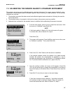
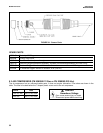
1. Unscrew the membrane retainer and remove the membrane assembly
and O-ring. See Figure 9-1.
2. Hold the sensor over a container with the cathode pointing down.
3. Remove the fill plug and allow the electrolyte solution to drain out.
4. Inspect the cathode. If it is tarnished, clean it by gently rubbing in the direction of the existing scratches (do
not use a circular motion) with 400-600 grit silicon carbide finishing paper. Rinse the cathode thoroughly with
water.
5. Wrap the plug with several turns of pipe tape and set aside.
6. Prepare a new membrane. Hold the membrane assembly with the cup formed by the membrane and mem-
brane holder pointing up. Fill the cup with electrolyte solution. Leave the membrane assembly filled with elec-
trolyte solution and set it aside.
7. Hold the sensor at about a 45-degree angle with the cathode end pointing up. Add electrolyte solution through
the fill hole until the liquid overflows. Tap the sensor near the threads to release trapped air bubbles. Add more
electrolyte solution if necessary.
8. Place the fill plug in the electrolyte port and begin screwing it in. After several threads have engaged, rotate
the sensor so that the cathode is pointing up and continue tightening the fill plug. Do not overtighten.
9. Place a new O-ring in the groove around the cathode post. Cover the holes at the base of the cathode stem
with several drops of electrolyte solution.
10. Insert a small blunt probe, like a toothpick with the end cut off, through the pressure equalizing port. See
Figure 9-1.
NOTE
Do not use a sharp probe. It will puncture the bladder and destroy the sensor.
Gently press the probe against the bladder several times to force liquid through the holes at the base of the
cathode stem. Keep pressing the bladder until no air bubbles can be seen leaving the holes. Be sure the holes
remain covered with electrolyte solution.
11. Place a drop of electrolyte solution on the cathode, then place the membrane assembly over the cathode.
Screw the membrane retainer in place.
12. The sensor may require several hours operating at the polarizing voltage to equilibrate after the electrolyte
solution has been replenished.
NOTE
If the membrane and electrolyte solution were replaced, check the sensor performance
before reassembling the sensor and washer head assembly. To zero the sensor, refer to
Section 7.2. To perform an air calibration, refer to Section 7.3.
CAUTION
Fill solution may cause
irritation. May be harm-
ful if swallowed. Read
and follow manual.
51