


Daniel 3410 Series Ultrasonic Gas Flow Meter Installation Manual Section 4: Configuration
3-9000-759 Rev D June 2014
Using AMS Device Manager to configure the meter 85
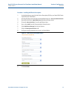
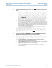
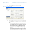
4. After all of the data shown below is entered, click Apply to write the parameters to the
meter.
a. Click the
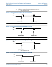
Frequency/Digital Outputs tab to configure Frequency/Digital Output 1,
2 and 3 Source and drive Mode. Select the Source for each Frequency/Digital
output and select the desired drive Mode. The Mode options are Open Collector
which requires an external excitation voltage and pull-up resistor or TTL mode
which outputs a 0-5 VDC signal (each Frequency output has an A and B output
phase). (Refresh Note: If changes are made to any Source variable on this page,
apply the changes and navigate to the Guided Setup page. Navigate back to the
Manual Setup for the changes to be reflected in other Manual Setup pages).
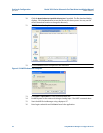
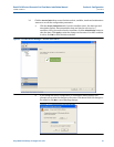
b. Click the
Frequency and Digital Output 1 tab to configure the Content, (flow)
Direction, Channel B Phase frequency output, Lag forward, Lead Reverse or Lead
Forward, Lag Reverse (Phase B lags Phase A while reporting forward flow and lead
Phase A while reporting reverse flow or the opposite), Digital Output 1 Channel A
Content and Polarity, Channel B Content and Polarity, Maximum Frequency, and
Lower and Upper Range Units of Measure.
c. Click the
Frequency and Digital Output 2 tab and repeat Step 3b to configure
Frequency and Digital Output 2 parameters.
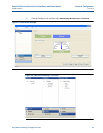
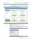
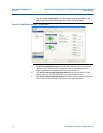
5. Click
Setup HART to configure the HART parameters (tag, date, descriptor, message
text, Final Assembly number, Poll address and number of response preambles are
displayed). After all of the data is entered click Apply to write the parameters to the
meter.
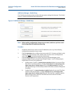
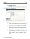
6. On the Overview page, click
Alert Setup and select the Flow Analysis tab and enable
Reverse Flow. Click the
OK button to return to the Overview page.
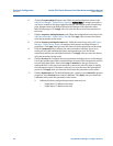
7. On the Overview page, click the
Service Tools tab and select the Variables tab. The Flow
Data, Path Information, Flow Totals, and All Variables data is populated after you are
connected to the meter.
a. Click the
Flow Data tab and view the Flow Direction (Forward or Reverse),
Average Flow and Average Sound Velocities values.
b. Click the
Path Information tab and view the Chord performance, Gain, SNR (Signal
to Noise Ratio) Signal strength (mV), and Noise (mV).
c. Click the
Flow Totals tab to view the volume totals (forward and reverse
uncorrected volume).