


ADSP-21369 EZ-KIT Lite Evaluation System Manual 2-17
EZ-KIT Lite Hardware Reference
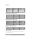
Board Reset Push Button (SW12)
The RESET push button (SW12) resets all of the ICs on the board. The only
exception is the USB interface chip (
U4). The chip is not being reset when
the push button is pressed after the USB cable has been plugged in and
communication correctly initialized with the PC. After USB communica-
tion has been initialized, the only way to reset the USB is by powering
down the board.
Jumpers
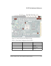
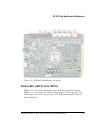
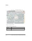
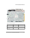
Figure 2-7 shows the locations and default settings of the EZ-KIT Lite
jumpers.
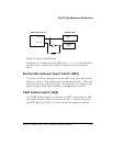
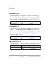
VCO Select Jumper (JP1)
The voltage controlled oscillator (VCO) select jumper (JP1) configures
the frequency selection of the on-board external PLL (
U39). When JP1 is
installed, the VCO output frequency is multiplied by a factor of 1.0. Con-
versely, when uninstalled, the VCO output frequency is multiplied by a
factor of 0.5 or divided in half. The jumper settings are shown in
Table 2-10.
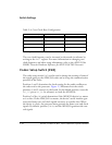
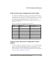
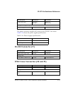
PB3 SW10 DAI19
PB4 SW9 DAI20
Table 2-9. Push Button Connections (Cont’d)
Push Button Label Push Button Reference Designator Processor Pin